|
twincrank
This linkage forms a twincrank. In general the coupler is moved exclusively translatoric and possesses a circular couplercurve
|

|
Antriebsstrang einer Schleifmaschine
Stirnradgetriebe zur Übersetzung der Antriebsdrehzahl und des -momentes
|

|
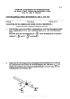
Antriebstrang einer Bohrmaschine
Antriebstrang einer Bohrmaschine in Form einer Kurbelschwinge
|

|
Beihauptlegemaschine
Das Bild zeigt eine Beihauptlegemaschine. Ausgestellt im Museum Zinkhütter Hof in Stolberg bei Aachen.
|

|
Bohrmaschine
Der Antrieb der Bohrmaschine ist der Elektromotor im hinteren Teil des Gestells. Über eine Stirnradstufe und ein Riemengetriebe wird die Bohrwelle angetrieben.
|

|
Dieselmotor Sendling
Das Bild zeigt einen Sendling Dieselmotor mit Riementrieb. Ausgestellt im Museum Zinkhütter Hof in Stolberg bei Aachen.
|

|
Drehbank
Drehbank zur Herstellung rotationssymmetrischer Bauteile
|

|
Druckwalze
Druckwalzen mit einstellbarem Hub zum Walzen von Werkstücken
|

|
Exzenterpresse
Schwere Exzenterpresse mit Riemenantrieb und einer Zahnradstufe
|

|
Exzenterpresse
Zu sehen ist eine schwere Exzenterpresse mit Riementrieb. Ausgestellt im Museum Zinkhütter Hof in Stolberg bei Aachen.
|

|
Fallhammer
In zwei Schienen geführter Fallhammer zur schmiedenden Bearbeitung von Werkstücken
|

|
Fallhammer
In zwei Schienen geführter Fallhammer zur schmiedenden Bearbeitung von Werkstücken
|

|
Fallhammer
In zwei Schienen geführter Fallhammer zur schmiedenden Bearbeitung von Werkstücken
|

|
Fräsmaschine
Das Bild zeigt eine Fräsmaschine zur Herstellung von Nadeln in der Textilindustrie
|

|
Fräsmaschine
Das Bild zeigt eine Fräsmaschine zur Herstellung von Nadeln in der Textilindustrie
|

|
Fräsmaschinen
Zwei Fräsmaschinen werden über eine gemeinsame Antriebwelle mit Hilfe von Riementrieben angetrieben.
|

|
Fräsmaschinen
Das Bild zeigt eine Fräsmaschine mit verschiedenen Antrieben. Ausgestellt im Museum Zinkhütter Hof in Stolberg bei Aachen.
|

|
Gratschleifmaschine
Zu sehen ist eine Schleifmaschine zum Entgraten von Werkstücken. Ausgestellt im Museum Zinkhütter Hof in Stolberg bei Aachen.
|

|
Kettenmaschine
In Kettenmaschinen werden Ketten hergestellt. Die Kettenmaschine schneidet den Draht auf die benötigte Länge und biegt ihn um einen Dorn, wodurch die typische Kettenform entsteht
|

|
Kettenmaschine
Kettenmaschine 3--In Kettenmaschinen werden Ketten hergestellt. Die Kettenmaschine schneidet den Draht auf die benötigte Länge und biegt ihn um einen Dorn, wodurch die typische Kettenform entsteht
|

|
Kettenmaschine
In Kettenmaschinen werden Ketten hergestellt. Die Kettenmaschine schneidet den Draht auf die benötigte Länge und biegt ihn um einen Dorn, wodurch die typische Kettenform entsteht
|

|
Kettenmaschine
In Kettenmaschinen werden Ketten hergestellt. Die Kettenmaschine schneidet den Draht auf die benötigte Länge und biegt ihn um einen Dorn, wodurch die typische Kettenform entsteht
|

|
Kettenmaschine
In Kettenmaschinen werden Ketten hergestellt. Die Kettenmaschine schneidet den Draht auf die benötigte Länge und biegt ihn um einen Dorn, wodurch die typische Kettenform entsteht
|

|
Leonardsatz
Der Leonardsatz ist ein Umformer zum Umformen eines Drehstromes in eine Gleichspannung
|

|
LKW-Motor MAN
Das Bild zeigt einen kompletten LKW-Motor der Firma MAN. Ausgestellt im Museum Zinkhütter Hof in Stolberg bei Aachen.
|

|
Maschine aus der Nadelproduktion
Das Bild zeigt eine Maschine aus der Nadelproduktion. Zu sehen ist der Fallhammer zum Umformen des Drahtes. Ausgestellt im Museum Zinkhütter Hof in Stolberg bei Aachen.
|

|
Papierschneidemaschine
Papierschneidemaschine mit Antriebsstrang in Form einer Kurbelschwinge mit einstellbarem Schwingenwinkel
|

|
Papierschneidemaschine
Papierschneidemaschine mit Antriebsstrang in Form einer Kurbelschwinge mit einstellbarem Schwingenwinkel
|

|
Prägewerkzeug
Zu sehen ist eine Prägemaschine mit abgebildetem Antriebshammer. Ausgestellt im Museum Zinkhütter Hof in Stolberg bei Aachen.
|

|
Presse
Presse mit Sprindelantrieb und zwei Führungsschienen (Firma Glas)
|

|
Presse
Das Bild zeigt eine Presse mit Sperrgetriebe und manuellem Kurbelantrieb. Ausgestellt im Museum Zinkhütter Hof in Stolberg bei Aachen.
|

|
Kaiserpresse
Zu sehen ist der Riementrieb der Kaiserpresse (Firma Kaiser). Ausgestellt im Museum Zinkhütter Hof in Stolberg bei Aachen.
|

|
Reduziermaschine
Verringerung der Querschnittsfläche von Drähten und Rohren
|

|
Richtmaschine
Zu sehen ist eine Richtmaschine zum Richten von Rohren. Ausgestellt im Museum Zinkhütter Hof in Stolberg bei Aachen.
|

|
Richtmaschine
Richtmaschinen dienen zum Verbessern undoder Korrigieren der Maßhaltigkeit eines Werkstückes
|

|
Richtmaschine
Das Bild zeigt eine Richtmaschine zum Richten von Rohren. Ausgestellt im Museum Zinkhütter Hof in Stolberg bei Aachen.
|

|
Riementrieb der Kaiserpresse
Das Bild zeigt den Riementrieb der Kaiserpresse von der Firma Kaiser. Ausgestellt im Museum Zinkhütter Hof in Stolberg bei Aachen.
|

|
Riementrieb
Zu sehen ist eine alte Maschine mit Riementrieb als Vorschaltgetriebe. Ausgestellt im Museum Zinkhütter Hof in Stolberg bei Aachen.
|

|
Rondenschere
Maschine zum Herstellen von Ronden (Zylinder mit geringer Höhe im Vergleich zum Durchmesser) mit Handkurbel als Antrieb
|

|
Schermaschine
Schermaschine zum Trennen von kleinquerschnittigen Werkstücken
|

|
Schleifmaschine
Das Bild zeigt eine Schleifmaschine mit Stirnradstufe als Antrieb. Ausgestellt im Museum Zinkhütter Hof in Stolberg bei Aachen.
|

|
Schleifmaschine
Zu sehen ist eine Schleifmaschine mit Stirnradstufe als Antrieb. Ausgestellt im Museum Zinkhütter Hof in Stolberg bei Aachen.
|

|
Seilwinde
Das Bild zeigt eine Seilwinde mit Antriebskurbel und Sperrgetriebe. Ausgestellt im Museum Zinkhütter Hof in Stolberg bei Aachen.
|

|
Spindelpresse
Die abgebildete Spindelpresse wandelt eine Rotation (Antriebsbewegung) in eine Translation (Abtriebsbewegung) um und leitet dadurch einen Pressvorgang ein.
|

|
Spitzenschleifmaschine
Die Spitzenschleifmaschine zum Anschleifen der Nadeln wird über einen Riementrieb angetrieben.
|

|
Tuchnähmaschine
Das Bild zeigt eine Tuchnähmaschine mit Antrieb per Fusspedal. Ausgestellt im Museum Zinkhütter Hof in Stolberg bei Aachen.
|

|
Walzenstuhl
Walzenstuhl zum Zerkleinern von Mahlgut. Der Antrieb erfolgt manuell über eine Stirnradstufe
|

|
Walzenstuhl
Walzenstuhl zum Zerkleinern von Mahlgut. Der Antrieb erfolgt über eine Stirnradstufe
|

|
Waschmaschine
Zwischen den verschiedenen Arbeitsgängen müssen die Rohlinge gereinigt werden. Dies geschieht in speziellen Waschmaschinen. Anschließend werden sie mit Sägemehl in Trommeln getrocknet.
|

|
Wasserpumpe
Das Bild zeigt eine Wasserpumpe mit vorgeschaltetem Schneckengetriebe. Ausgestellt im Museum Zinkhütter Hof in Stolberg bei Aachen.
|

|
Außeninnenschwinge
Darstellung einer Außeninnenschwinge. Zu sehen ist eine Doppelaußenschwinge mit einer Spitze und einem Selbstberührpunkt 93
|

|
Kurbelschleife
Kurbelschleife mit schwingender Schleife mit einem Knotenpunkt 23
|

|
Schwingschleife
Darstellung einer Schwingschleife mit zwei Knotenpunkten
|

|
Geschwindigkeit eines Gliedpunktes im Bezugssystem
Bewegung des Gliedpunkt A der bewegten Ebene E auf seiner Bahn kA im festen x, y – Bezugssystem. Die momentane Lage des Gliedpunktes A wird durch den Orts¬vektor sA gekennzeichnet. Die mo-mentane Geschwindigkeit vA des Gliedpunktes A beschreibt dabei die zeitliche Änderung seines Ortes. Sie ist dementsprechend die Ableitung des Ortsvektors sA nach der Zeit und da¬mit selbst ein Vektor.
|

|
Drehbewegung eines Gliedes im Bezugssystem
Die Winkelgeschwindigkeit beschreibt die zeitliche Änderung der Orientierung eines Glie¬des relativ zu einem Bezugssystem. Ist diese Orientierung zum Beispiel durch einen Winkel zwischen vereinbarten Achsen zweier Systeme, so ist die Winkelgeschwindigkeit die Ableitung des Drehwinkels nach der Zeit und wird durch einen Vektor gekennzeichnet, der bei der ebenen Bewegung senkrecht auf der Bezugsebene steht, also parallel zur z-Achse ist. Weist er in Richtung der positiven z Achse, so entspricht das dem mathematisch positiven Drehsinn, also entgegen dem Uhrzeigersinn.
|

|
Lokaler Hodograph der Bewegung eines Gliedpunktes
Um eine gute Übersicht über den Geschwindigkeitsverlauf eines Gliedpunktes zu erhalten, ist es sinnvoll, an aufeinander¬folgenden Punkten der Bahnkurve den ent¬sprechenden Geschwin-digkeitsvektor um 90° gedreht, also senkrecht auf der Bahntangente stehend zu zeichnen. Die verbindende Kurve der Vektorspitzen wird als "lokaler Hodograph" bezeichnet.
|

|
Hodograph
Beispiel eines lokalen Hodographen für den Schieber einer Hochleistungspresse.
|

|
Reine Drehung eines Getriebegliedes a)räumliche Darstellung
Im Allgemeinen setzt sich der Geschwindigkeitszustand einer bewegten Ebene aus einer gleichzeitigen Drehung und Schiebung zusammen. Reine Drehung und reine Schiebung sind daher spezielle Bewegungen einer Gliedebene, für die sich besonders einfache Verhältnisse ergeben.
Reine Drehung liegt bei einer Drehung um eine feste Drehachse vor
|

|
Reine Drehung eines Getriebegliedes b)ebene
Bei reiner Drehung bewegen alle Glied¬punkte entlang konzentrische Kreise um den festen Drehpunkt A0. Die Geschwindigkeit eines Punktes A steht senkrecht zur Winkelgeschwindigkeit und senkrecht zur Verbindungslinie vom Drehpunkt A0
|

|
Reine Schiebung eines Getriebegliedes
Reine Schiebung einer Gliedebene liegt vor, wenn seine Winkelgeschwindigkeit dauernd gleich Null ist. Die Gliedebene wird während der Bewegung nicht gedreht, sondern nur parallel verschoben.
|

|
Aufteilung einer allgemeinen Bewegung in Schiebung und Drehung
Jede allgemeine Bewegung eines Gliedes kann aufgeteilt werden in eine Schiebung des Gliedes mit der Geschwindigkeit eines beliebigen Gliedpunktes und eine Drehung des Gliedes mit seiner Winkelgeschwindigkeit relativ zur Bezugsebene um diesen Punkt (Satz von Euler). die Geschwindigkeit vA eines Punktes A als Schiebekomponente betrachtet und der Vektor vom Punkt A zum Punkt B mit AB bezeichnet, so entsteht durch die Drehung des Gliedes um A mit der Winkelgeschwindigkeit die senkrecht zum Vektor AB gerichtete Geschwindigkeitskomponente. Aus der Überlagerung von Schiebung und Drehung ergibt sich schließlich die resultierende Geschwindigkeit vB des Punktes B relativ zur Bezugsebene in Richtung der Bahntangente tB.
|

|
Geschwindigkeitspol P einer allgemeinen Bewegung
Jede allgemeine Bewegung kann momentan als Drehung um einen bestimmten Punkt - den Geschwindigkeitspol P - aufgefasst werden. Im Gegensatz zur reinen Drehung ist die Lage dieses Geschwindigkeitspoles als momentaner Drehpunkt jedoch relativ zum bewegten Glied und relativ zum Bezugsglied veränderlich. Aufgrund der momentanen Drehung um den Geschwindigkeitspol sind die Geschwindigkeiten aller Gliedpunkte senkrecht zu den je¬weiligen Polstrahlen vom Pol zum betrachteten Punkt gerichtet, d.h. alle Bahnnormalen schneiden sich im Pol, und die Geschwindigkeitsbeträge sind proportional zum jeweiligen Polabstand
|

|
Ermittlung von Geschwindigkeiten im Lageplan
Verbindet man z.B. im Lageplan einer allgemein bewegten Ebene die Spitzen der Geschwindigkeitsvektoren, so entsteht eine Figur, die der Verbindungslinie der entsprechenden Gliedpunkte gleichsinnig ähnlich ist. Für grafische Konstruktionen ist dabei besonders wichtig, dass die Vektorspitzen von Punkten, die auf einer Geraden liegen, eben¬falls auf einer Geraden liegen.
|

|
Beweis für die Ermittlung von Geschwindigkeiten im Lageplan
Der Beweis für die Entstehung einer Figur, die der Verbindungslinie der entsprechenden Gliedpunkte gleichsinnig ähnlich ist.
|

|
Ermittlung von Geschwindigkeiten im Geschwindigkeitsplan
Trägt man Geschwindigkeitsvektoren einer bewegten Ebene unter Beibehaltung ihrer Richtung im Lageplan von einem beliebigen Punkt P´ aus ab, so erhält man den Geschwindigkeitsplan Die Verbindung dieser Vektorspitzen bildet eine Figur, die der Verbindungslinie der entsprechenden Gliedpunkte ähnlich ist und gegenüber dieser um 90° im Sinne der Winkelgeschwindigkeit gedreht liegt
|

|
Satz von den gedrehten Geschwindigkeiten
Werden die Geschwindigkeitsvektoren von Punkten einer bewegten Ebene alle um 90° gedreht in Richtung der Polstrahlen gezeichnet, so ist jede Verbindungsgerade zweier Vektorspitzen dieser gedrehten Geschwindigkeiten parallel zur Verbindungsgeraden der entsprechenden Gliedpunkte.
|

|
Gang- und Rastpolbahn einer allgemeinen Bewegung
Gangpolbahn kg: Folge der Geschwindigkeitspole (Momentanpole) in der bewegten Ebene.
Rastpolbahn kr: Folge der Geschwindigkeitspole (Momentanpole) in der festen Ebene (Bezugsebene)
|

|
Rechtwinkliger Doppelschieber und Kardankreispaar
Beim rechtwinkligen Doppelschieber entstehen als Sonderformen von Polbahnen Kreise
|

|
Gleichschenklige Schubkurbel
Mit der gleichschenkligen Schubkurbel (Abmessungen (M0M)=MB=MA) wird der Koppelpunkt A auf einer geradlinigen Bahn geführt
|

|
Antiparallelkurbel 2. Art
Bei der Antiparallelkurbel ist die Summe der Abstände konstant
(A0P20)+(P20B0)=(BP20)+(P20A)=(A0A)=(B0B)=const.
|

|
Elliptisches Zahnradpaar
Führt man bei einer Antiparallelkurbel einen Gestellwechsel durch, bei dem das Getriebe¬glied 1 oder 3 zum Gestell wird, so treten die Ellipsen als Relativpolbahnen der Getriebe¬glieder 2 und 4 auf. Diese Relativpolbahnen werden als Elliptische Zahnräder ausgeführt und zur Erzeugung einer ungleichförmig fortlaufenden Drehbewegung verwendet
|

|
Einschubteil einer Flaschenreinigungsmaschine
Anwendungsbeispiel von Ellipsenräder in Form einer Einschubvorrichtung einer Flaschenreinigungsmaschine.
|

|
Relativbewegung von drei Gliedebenen
Bewegung des Punkt A auf der Ebene 2 relativ zur Ebene 1 mit der Geschwindigkeit vA21 und der Geschwindigkeit vA10 auf E1 relativ zu E0. Die Geschwindigkeit des Punktes A auf E2 relativ zur Bezugsebene setzt sich aus beiden genannten Geschwindigkeiten zusammen.
Führungsgeschwindigkeit vf = vA10
Relativgeschwindigkeit vr = vA21
Absolutgeschwindigkeit vA = vA20
|

|
Relativpole bei der Relativbewegung von drei Gliedebenen
Bei mehreren Ebenen kann die Bewegung jeder Ebene relativ zu jeder anderen als Drehung um einen entsprechenden Relativpol aufgefasst werden. Man bezeichnet z.B. den Pol für die relative Drehung der beiden Ebenen E1 und E2 als P12 oder P21 (kurz 12 oder 21). Dabei ist wichtig festzuhalten, dass es sich bei dem Relativpol um eine momentane Lage handelt, die nur für den momentanen Geschwindigkeitszustand gilt. Daher wird der Relativpol oft auch als Momentanpol bezeichnet wird. Bei der Bewegung der beiden Ebenen E1 und E2 relativ zueinander und zur Bezugsebene E0 gibt es insgesamt die drei Relativpole P10, P20 und P21
|

|
Beispiel eines viergliedrigen Kurbelgetriebes mit zwei möglichen zugehörigen Hilfsfiguren
Zur Bestimmung der Relativpole wird eine Hilfsfigur benutzt, die so viele Eckpunkte besitzt wie es der Anzahl der Getriebeglieder des betrachteten Getriebes entspricht. Voll ausge¬zogene Verbindungsgeraden zwischen diesen Eckpunkten entsprechen dann den Gelenken des Getriebes.
|

|
|

|
Relativpole 52
Beispiel zur Bestimmung unbekannter Relativpole eines 6gliedrigen Getriebes
|

|
Relativpole
Beispiel zur Bestimmung unbekannter Relativpole eines Räder- und Kurbelgetriebes
|

|
Konstruktive Skizze und kinematisches Schema des Pressengetriebes
Getriebe zum Antrieb einer Tiefziehpresse. Auf Grund der technologischen Forderungen für den Tiefziehvorgang sowie auf Grund möglichst kurzer Taktzeiten soll der Stempel S aus seiner oberen Umkehrlage mit mittlerer Geschwindigkeit an das Werkstück heranfahren, dann mit geringer und möglichst konstanter Geschwindigkeit den Ziehvorgang ausführen und aus der unteren Umkehrlage schnell zurücklaufen. Bei diesem Getriebe handelt es sich, wenn man den Ritzelantrieb zunächst vernachlässigt, um ein siebengliedriges Kurbelgetriebe, das keine Viergelenkkette enthält. Das fünfgliedrige Teil¬getriebe A0 ACBB0, dessen Gelenkpunkt C als Anlenkpunkt des Zweischlages aus Pleuel 5 und Schieber 6 verwendet wird, hat den Laufgrad F=2. Der Zwanglauf wird durch Antrieb an den beiden Kurbeln 1 und 2 mit gleicher Übersetzung durch eine zentrale Antriebswelle erreicht. Die beiden Kurbeln laufen durch die Zahnräder synchron angetrieben.
|

|
Geschwindigkeitsermittlung nach Euler
Bestimmung der Geschwindigkeiten im kinematischen Schema des Getriebes des Pressengetriebes nach Euler
|

|
Lokaler Hodograph des Pressenstempels
Darstellung des lokalen Hodografen des Gelenkpunktes D des Pressengetriebes.
|

|
Francisco Javier Campa, assistant profesor of the UPV/EHU.
Portrait of Francisco Javier Campa, assistant profesor of the University of the Basque Country (UPV/EHU).
|

|
Erik Macho, assistant lecturer at the University of the Basque Country
Portrait corresponding to Erik Macho, assistant lecturer at the University of the Basque Country (UPV/EHU).
|

|
Mikel Díez, assitant lecturer of the University of the Basque Country.
Portrait of Mikel Díez, assistant lecturer of the University of the Basque Country (UPV/EHU).
|

|
|

|
|

|
|

|
|

|
|

|
Javier Corral Saíz, Assistant Profesor of the UPV/EHU.
Portrait of Javier Corral Saíz, Assistant Profesor of University of the Basque Country (UPV/EHU).
|

|
Saioa Herrero, PhD. Student at the University of the Basque Country
Portrait of Saioa Herrero, PhD. Student at the University of the Basque Country (UPV/EHU).(1986-)
|

|
Hight adjustable table support
The motion device relates to a mechanism for the height adjustment of a table support. The height adjustment is based on a linkage with 8 links and 10 joints, which can be driven by a hand crank in combination with a chain drive. The degree of freedom of the mechanism is F = 1.
|

|
Doublerocker, crankrocker V-form 1
Typical couplercurve of the crankrocker/revolving doublerocker.
Couplercurve in V-form
|

|
Doublerocker, crankrocker V-form 2
Typical couplercurve of the crankrocker/revolving doublerocker.
Couplercurve in V-form
|

|
Doublerocker, crankrocker V-form 3
Typical couplercurve of the crankrocker/revolving doublerocker.
Couplercurve in V-form
|

|
Four bar linkage
The data describes a four bar linkage whose dimensions can be variegated. In this interactive worksheet the four link lengths, two coupler-triangle lengths and the angle of drive are able to be changed. For moving the mechanism the point A can be displaced on a reference circle around A0. The adaption of the distances AAo and AB... can be made by moving the left points in horizontal direction of each line displayed below. Thereby the modification of the cam coupler is directly recognizable.
|

|
Doublerocker, crankrocker V-form 5
Typical couplercurve of the crankrocker/revolving doublerocker.
Couplercurve in V-form
|

|
Doublerocker, crankrocker V-form 6
Typical couplercurve of the crankrocker/revolving doublerocker.
Couplercurve in V-form
|

|
Doublerocker, crankrocker Bananaform 8
Typical couplercurve of the crankrocker/revolving doublerocker.
Couplercurve in bananaform
|

|
Doublerocker, crankrocker Bananaform 9
Typical couplercurve of the crankrocker/revolving doublerocker.
Couplercurve in bananaform
|

|
Doublerocker, crankrocker Bananaform 10
Typical couplercurve of the crankrocker/revolving doublerocker.
Couplercurve in bananaform
|

|
Doublerocker, crankrocker dropform 37
Typical couplercurve of the crankrocker/revolving doublerocker.
Couplercurve in drop form
|

|
Doublerocker, crankrocker dropform 36
Typical couplercurve of the crankrocker/revolving doublerocker.
Couplercurve in drop form
|

|
Doublerocker, crankrocker dropform 35
Typical couplercurve of the crankrocker/revolving doublerocker.
Couplercurve in drop form
|

|
Doublerocker, crankrocker dropform 34
Typical couplercurve of the crankrocker/revolving doublerocker.
Couplercurve in drop form
|

|
Doublerocker, crankrocker dropform 33
Typical couplercurve of the crankrocker/revolving doublerocker.
Couplercurve in drop form
|

|
Doublerocker, crankrocker dropform 32
Typical couplercurve of the crankrocker/revolving doublerocker.
Couplercurve in drop form
|

|
Doublerocker, crankrocker dropform 31
Typical couplercurve of the crankrocker/revolving doublerocker.
Couplercurve in drop form
|

|
Doublerocker, crankrocker dropform 30
Typical couplercurve of the crankrocker/revolving doublerocker.
Couplercurve in drop form
|

|
Doublerocker, crankrocker airfoil form 29
Typical couplercurve of the crankrocker/revolving doublerocker.
Couplercurve in airfoil form
|

|
Doublerocker, crankrocker airfoil form 28
Typical couplercurve of the crankrocker/revolving doublerocker.
Couplercurve in airfoil form
|

|
Doublerocker, crankrocker airfoil form 27
Typical couplercurve of the crankrocker/revolving doublerocker.
Couplercurve in airfoil form
|

|
Doublerocker, crankrocker airfoil form 26
Typical couplercurve of the crankrocker/revolving doublerocker.
Couplercurve in airfoil form
|

|
Doublerocker, crankrocker airfoil form 25
Typical couplercurve of the crankrocker/revolving doublerocker.
Couplercurve in airfoil form
|

|
Doublerocker, crankrocker airfoil form 24
Typical couplercurve of the crankrocker/revolving doublerocker.
Couplercurve in airfoil form
|

|
Doublerocker, crankrocker airfoil form 23
Typical couplercurve of the crankrocker/revolving doublerocker.
Couplercurve in airfoil form
|

|
Doublerocker, crankrocker airfoil form 22
Typical couplercurve of the crankrocker/revolving doublerocker.
Couplercurve in airfoil form
|

|
Doublerocker, crankrocker airfoil form 21
Typical couplercurve of the crankrocker/revolving doublerocker.
Couplercurve in airfoil form
|

|
Doublerocker, crankrocker airfoil form 20
Typical couplercurve of the crankrocker/revolving doublerocker.
Couplercurve in airfoil form
|
![]()
|
Doublerocker, crankrocker airfoil form 19
Typical couplercurve of the crankrocker/revolving doublerocker.
Couplercurve in airfoil form
|

|
Doublerocker, crankrocker airfoil form 18
Typical couplercurve of the crankrocker/revolving doublerocker.
Couplercurve in airfoil form
|

|
Doublerocker, crankrocker with two spikes 69
Typical couplercurve of the crankrocker/revolving doublerocker.
Couplercurve in two spikes form
|

|
Doublerocker, crankrocker with two spikes 68
Typical couplercurve of the crankrocker/revolving doublerocker.
Couplercurve in two spikes form
|

|
Doublerocker, crankrocker with two spikes 67
Typical couplercurve of the crankrocker/revolving doublerocker.
Couplercurve in two spikes form
|

|
Doublerocker, crankrocker with two spikes 66
Typical couplercurve of the crankrocker/revolving doublerocker.
Couplercurve in two spikes form
|

|
Doublerocker, crankrocker with two junctions and one spike 76
Typical couplercurve of the crankrocker/revolving doublerocker.
Couplercurve in two junctions and one spike form
|

|
Doublerocker, crankrocker with two junctions 53
Typical couplercurve of the crankrocker/revolving doublerocker.
Couplercurve in two junctions form
|

|
Doublerocker, crankrocker with two junctions 52
Typical couplercurve of the crankrocker/revolving doublerocker.
Couplercurve in two junctions form
|

|
Doublerocker, crankrocker with two junctions 51
Typical couplercurve of the crankrocker/revolving doublerocker.
Couplercurve in two junctions form
|

|
Doublerocker, crankrocker with one spike and one self-tangency 78
Typical couplercurve of the crankrocker/revolving doublerocker.
Couplercurve in one spike with one self-tangency form
|

|
Doublerocker, crankrocker with one spike and one self-tangency 77
Typical couplercurve of the crankrocker/revolving doublerocker.
Couplercurve in one spike with one self-tangency form
|

|
Doublerocker, crankrocker with one spike 65
Typical couplercurve of the crankrocker/revolving doublerocker.
Couplercurve in one spike form
|

|
Doublerocker, crankrocker with one spike 64
Typical couplercurve of the crankrocker/revolving doublerocker.
Couplercurve in one spike form
|

|
Doublerocker, crankrocker with one spike 63
Typical couplercurve of the crankrocker/revolving doublerocker.
Couplercurve in one spike form
|

|
Doublerocker, crankrocker with one spike 61
Typical couplercurve of the crankrocker/revolving doublerocker.
Couplercurve in one spike form
|

|
Doublerocker, crankrocker with one spike 60
Typical couplercurve of the crankrocker/revolving doublerocker.
Couplercurve in one spike form
|

|
Doublerocker, crankrocker with one spike 59
Typical couplercurve of the crankrocker/revolving doublerocker.
Couplercurve in one spike form
|

|
Doublerocker, crankrocker with one spike 58
Typical couplercurve of the crankrocker/revolving doublerocker.
Couplercurve in one spike form
|

|
Doublerocker, crankrocker with one spike 57
Typical couplercurve of the crankrocker/revolving doublerocker.
Couplercurve in one spike form
|

|
Doublerocker, crankrocker with one spike 56
Typical couplercurve of the crankrocker/revolving doublerocker.
Couplercurve in one spike form
|

|
Doublerocker, crankrocker with one spike 55
Typical couplercurve of the crankrocker/revolving doublerocker.
Couplercurve in one spike form
|

|
Doublerocker, crankrocker with one self-tangency 71
Typical couplercurve of the crankrocker/revolving doublerocker.
Couplercurve in one self-tangency form
|

|
Doublerocker, crankrocker with one self-tangency 70
Typical couplercurve of the crankrocker/revolving doublerocker.
Couplercurve in one self-tangency form
|

|
Doublerocker, crankrocker with one junction and two spikes 74
Typical couplercurve of the crankrocker/revolving doublerocker.
Couplercurve in one junction and two spikes form
|

|
Doublerocker, crankrocker with one junction and one spikes 73
Typical couplercurve of the crankrocker/revolving doublerocker.
Couplercurve in one junction and one spike form
|

|
Doublerocker, crankrocker with one junction and one spikes 72
Typical couplercurve of the crankrocker/revolving doublerocker.
Couplercurve in one junction and one spike form
|

|
Doublerocker, crankrocker with one junction and one self-tangency 75
Typical couplercurve of the crankrocker/revolving doublerocker.
Couplercurve in one junction and one self-tangency form
|

|
Doublerocker, crankrocker with one junction 50
Typical couplercurve of the crankrocker/revolving doublerocker.
Couplercurve in one junction form
|

|
Doublerocker, crankrocker with one junction 49
Typical couplercurve of the crankrocker/revolving doublerocker.
Couplercurve in one junction form
|

|
Doublerocker, crankrocker with one junction 48
Typical couplercurve of the crankrocker/revolving doublerocker.
Couplercurve in one junction form
|

|
Doublerocker, crankrocker with one junction 47
Typical couplercurve of the crankrocker/revolving doublerocker.
Couplercurve in one junction form
|

|
Doublerocker, crankrocker with one junction 46
Typical couplercurve of the crankrocker/revolving doublerocker.
Couplercurve in one junction form
|

|
Doublerocker, crankrocker with one junction 45
Typical couplercurve of the crankrocker/revolving doublerocker.
Couplercurve in one junction form
|

|
Doublerocker, crankrocker with one junction 44
Typical couplercurve of the crankrocker/revolving doublerocker.
Couplercurve in one junction form
|

|
Doublerocker, crankrocker with one junction 43
Typical couplercurve of the crankrocker/revolving doublerocker.
Couplercurve in one junction form
|

|
Doublerocker, crankrocker with one junction 42
Typical couplercurve of the crankrocker/revolving doublerocker.
Couplercurve in one junction form
|

|
Doublerocker, crankrocker with one junction 41
Typical couplercurve of the crankrocker/revolving doublerocker.
Couplercurve in one junction form
|

|
Doublerocker, crankrocker with one junction 40
Typical couplercurve of the crankrocker/revolving doublerocker.
Couplercurve in one junction form
|

|
Doublerocker, crankrocker with one junction 39
Typical couplercurve of the crankrocker/revolving doublerocker.
Couplercurve in one junction form
|

|
Doublerocker, crankrocker with one junction 38
Typical couplercurve of the crankrocker/revolving doublerocker.
Couplercurve in one junction form
|

|
Doublerocker, crankrocker with three junctions 54
Typical couplercurve of the crankrocker/revolving doublerocker.
Couplercurve in three junctions form
|

|
Doublerocker, crankrocker in elliptical shape 17
Typical couplercurve of the crankrocker/revolving doublerocker.
Couplercurve in elliptical shape
|

|
Doublerocker, crankrocker in elliptical shape 16
Typical couplercurve of the crankrocker/revolving doublerocker.
Couplercurve in elliptical shape
|

|
Doublerocker, crankrocker in elliptical shape 15
Typical couplercurve of the crankrocker/revolving doublerocker.
Couplercurve in elliptical shape
|

|
Doublerocker, crankrocker in elliptical shape 14
Typical couplercurve of the crankrocker/revolving doublerocker.
Couplercurve in elliptical shape
|

|
Doublerocker, crankrocker in elliptical shape 13
Typical couplercurve of the crankrocker/revolving doublerocker.
Couplercurve in elliptical shape
|

|
Doublerocker, crankrocker in elliptical shape 12
Typical couplercurve of the crankrocker/revolving doublerocker.
Couplercurve in elliptical shape
|

|
Doublerocker, crankrocker in elliptical shape 11
Typical couplercurve of the crankrocker/revolving doublerocker.
Couplercurve in elliptical shape
|

|
double crank without any distinct points 3
Typical couplercurve of the double crank without any distinct points. The curve has the form of a double crank without any distinct points 3
|

|
double crank without any distinct points 2
Typical couplercurve of the double crank without any distinct points. The curve has the form of a double crank without any distinct points 2
|

|
double crank without any distinct points 1
Typical couplercurve of the double crank without any distinct points. The curve has the form of a double crank without any distinct points 1
|

|
Double crank with a spike 8
Typical couplercurve of the double crank witha spike. The curve has the form of a double crank witha spike
|

|
Doublekurve with a junction 6
Typical couplercurve of the double crank witha junction. The curve has the form of a double crank witha junction 6
|

|
Doublekurve with a junction 5
Typical couplercurve of the double crank witha junction. The curve has the form of a double crank witha junction 5
|

|
Doublekurve with a junction 4
Typical couplercurve of the double crank witha junction. The curve has the form of a double crank witha junction 4
|

|
Doublekurve with three junctions 7
Typical couplercurve of the double crank with three junctions. The curve has the form of a double crank with three junctions 7
|

|
Doublekurve with a junction and self-tangency 9
Typical couplercurve of the double crank with a junction and self-tangency. The curve has the form of a double crank with a junction and self-tangency
|

|
inside rocker/ doubleoutside rocker without special points 15
Typical couplercurve of a outside inside rocker/ doubleoutside rocker without special points. The curve has the form of a outside inside rocker, double outside rocker/crankrocker without special points
|

|
inside rocker/ doubleoutside rocker without special points 14
Typical couplercurve of a outside inside rocker/ doubleoutside rocker without special points. The curve has the form of a outside inside rocker, double outside rocker/crankrocker without special points
|

|
inside rocker/ doubleoutside rocker without special points 13
Typical couplercurve of a outside inside rocker/ doubleoutside rocker without special points. The curve has the form of a outside inside rocker, double outside rocker/crankrocker without special points
|

|
inside rocker/ doubleoutside rocker without special points 12
Typical couplercurve of a outside inside rocker/ doubleoutside rocker without special points. The curve has the form of a outside inside rocker, double outside rocker/crankrocker without special points
|

|
inside rocker/ doubleoutside rocker without special points 11
Typical couplercurve of a outside inside rocker/ doubleoutside rocker without special points. The curve has the form of a outside inside rocker, double outside rocker/crankrocker without special points
|

|
inside rocker/ doubleoutside rocker without special points 10
Typical couplercurve of a outside inside rocker/ doubleoutside rocker without special points. The curve has the form of a outside inside rocker, double outside rocker/crankrocker without special points
|

|
inside rocker/ doubleoutside rocker without special points 9
Typical couplercurve of a outside inside rocker/ doubleoutside rocker without special points. The curve has the form of a outside inside rocker, double outside rocker/crankrocker without special points
|

|
inside rocker/ doubleoutside rocker without special points 8
Typical couplercurve of a outside inside rocker/ doubleoutside rocker without special points. The curve has the form of a outside inside rocker, double outside rocker/crankrocker without special points
|

|
inside rocker/ doubleoutside rocker without special points 7
Typical couplercurve of a outside inside rocker/ doubleoutside rocker without special points. The curve has the form of a outside inside rocker, double outside rocker/crankrocker without special points
|

|
inside rocker/ doubleoutside rocker without special points 6
Typical couplercurve of a outside inside rocker/ doubleoutside rocker without special points. The curve has the form of a outside inside rocker, double outside rocker/crankrocker without special points
|

|
inside rocker/ doubleoutside rocker without special points 5
Typical couplercurve of a outside inside rocker/ doubleoutside rocker without special points. The curve has the form of a outside inside rocker, double outside rocker/crankrocker without special points
|

|
inside rocker/ doubleoutside rocker without special points 4
Typical couplercurve of a outside inside rocker/ doubleoutside rocker without special points. The curve has the form of a outside inside rocker, double outside rocker/crankrocker without special points
|

|
inside rocker/ doubleoutside rocker without special points 3
Typical couplercurve of a outside inside rocker/ doubleoutside rocker without special points. The curve has the form of a outside inside rocker, double outside rocker/crankrocker without special points
|

|
inside rocker/ doubleoutside rocker without special points 2
Typical couplercurve of a outside inside rocker/ doubleoutside rocker without special points. The curve has the form of a outside inside rocker, double outside rocker/crankrocker without special points
|

|
Outside- inside rocker withot special points 1
Typical couplercurve of a outside inside rocker/ doubleoutside rocker without special points. The curve has the form of a outside inside rocker, double outside rocker/crankrocker without special points
|

|
inside rocker/ doubleoutside rocker with two nodes and one spike 92
Typical couplercurve of a outside inside rocker/ doubleoutside rocker with two nodes and one spike. The curve has the form of a outside inside rocker, double outside rocker/crankrocker with two nodes and one spike
|

|
inside rocker/ doubleoutside rocker with two nodes and one spike 91
Typical couplercurve of a outside inside rocker/ doubleoutside rocker with two nodes and one spike. The curve has the form of a outside inside rocker, double outside rocker/crankrocker with two nodes and one spike
|

|
inside rocker/ doubleoutside rocker with two nodes and one spike 90
Typical couplercurve of a outside inside rocker/ doubleoutside rocker with two nodes and one spike. The curve has the form of a outside inside rocker, double outside rocker/crankrocker with two nodes and one spike
|

|
inside rocker/ doubleoutside rocker with two nodes and one spike 89
Typical couplercurve of a outside inside rocker/ doubleoutside rocker with two nodes and one spike. The curve has the form of a outside inside rocker, double outside rocker/crankrocker with two nodes and one spike
|

|
inside rocker/ doubleoutside rocker with two nodes 47
Typical couplercurve of a outside inside rocker/ doubleoutside rocker with two nodes. The curve has the form of a outside inside rocker, double outside rocker/crankrocker with two nodes
|

|
inside rocker/ doubleoutside rocker with two nodes 46
Typical couplercurve of a outside inside rocker/ doubleoutside rocker with two nodes. The curve has the form of a outside inside rocker, double outside rocker/crankrocker with two nodes
|

|
inside rocker/ doubleoutside rocker with two nodes 44
Typical couplercurve of a outside inside rocker/ doubleoutside rocker with two nodes. The curve has the form of a outside inside rocker, double outside rocker/crankrocker with two nodes
|

|
3inside rocker/ doubleoutside rocker with two nodes 43
Typical couplercurve of a outside inside rocker/ doubleoutside rocker with two nodes. The curve has the form of a outside inside rocker, double outside rocker/crankrocker with two nodes
|

|
inside rocker/ doubleoutside rocker with two nodes 42
Typical couplercurve of a outside inside rocker/ doubleoutside rocker with two nodes. The curve has the form of a outside inside rocker, double outside rocker/crankrocker with two nodes
|

|
inside rocker/ doubleoutside rocker with one spike and self tangency 94
Typical couplercurve of a outside inside rocker/ doubleoutside rocker with one spike and self-tangency. The curve has the form of a outside inside rocker, double outside rocker/crankrocker with a spike and self-tangency
|

|
inside rocker/ doubleoutside rocker with one spike 67
Typical couplercurve of a outside inside rocker/ doubleoutside rocker with one spike. The curve has the form of a outside inside rocker, double outside rocker/crankrocker with a spike
|

|
Inside/ doubleoutside rocker with a spike 66
Typical couplercurve of a outside inside rocker/ doubleoutside rocker with one spike. The curve has the form of a outside inside rocker, double outside rocker/crankrocker with a spike
|

|
Inside/ doubleoutside rocker with a spike 65
Typical couplercurve of a outside inside rocker/ doubleoutside rocker with one spike. The curve has the form of a outside inside rocker, double outside rocker/crankrocker with a spike
|

|
Inside/ doubleoutside rocker with a spike 64
Typical couplercurve of a outside inside rocker/ doubleoutside rocker with one spike. The curve has the form of a outside inside rocker, double outside rocker/crankrocker with a spike
|

|
Inside/ doubleoutside rocker with a spike 63
Typical couplercurve of a outside inside rocker/ doubleoutside rocker with one spike. The curve has the form of a outside inside rocker, double outside rocker/crankrocker with a spike
|

|
Inside/ doubleoutside rocker with a spike 62
Typical couplercurve of a outside inside rocker/ doubleoutside rocker with one spike. The curve has the form of a outside inside rocker, double outside rocker/crankrocker with a spike
|

|
Inside/ doubleoutside rocker with a spike 61
Typical couplercurve of a outside inside rocker/ doubleoutside rocker with one spike. The curve has the form of a outside inside rocker, double outside rocker/crankrocker with a spike
|

|
Inside/ doubleoutside rocker with a spike 60
Typical couplercurve of a outside inside rocker/ doubleoutside rocker with one spike. The curve has the form of a outside inside rocker, double outside rocker/crankrocker with a spike
|

|
Inside/ doubleoutside rocker with a spike 59
Typical couplercurve of a outside inside rocker/ doubleoutside rocker with one spike. The curve has the form of a outside inside rocker, double outside rocker/crankrocker with a spike
|

|
Inside/ doubleoutside rocker with a spike 58
Typical couplercurve of a outside inside rocker/ doubleoutside rocker with one spike. The curve has the form of a outside inside rocker, double outside rocker/crankrocker with a spike
|

|
Inside/ doubleoutside rocker with a spike 57
Typical couplercurve of a outside inside rocker/ doubleoutside rocker with one spike. The curve has the form of a outside inside rocker, double outside rocker/crankrocker with a spike
|

|
Inside/ doubleoutside rocker with a spike 55
Typical couplercurve of a outside inside rocker/ doubleoutside rocker with one spike. The curve has the form of a outside inside rocker, double outside rocker/crankrocker with a spike
|

|
Inside/doubleoutside rocker with self-tangency 70
Typical couplercurve of a outside inside rocker/ doubleoutside rocker with self-tangency. The curve has the form of a outside inside rocker, double outside rocker/crankrocker with self-tangency
|

|
Inside/doubleoutside rocker with self-tangency 69
Typical couplercurve of a outside inside rocker/ doubleoutside rocker with self-tangency. The curve has the form of a outside inside rocker, double outside rocker/crankrocker with self-tangency
|

|
Inside/doubleoutside rocker with self-tangency 68
Typical couplercurve of a outside inside rocker/ doubleoutside rocker with self-tangency. The curve has the form of a outside inside rocker, double outside rocker/crankrocker with self-tangency
|

|
Inside/doubleoutside rocker with a node and two spikes 79
Typical couplercurve of a outside inside rocker/ doubleoutside rocker with one node and two spikes. The curve has the form of a outside inside rocker, double outside rocker/crankrocker with one node and two spikes
|

|
Inside/doubleoutside rocker with a node and two spikes 78
Typical couplercurve of a outside inside rocker/ doubleoutside rocker with one node and two spikes. The curve has the form of a outside inside rocker, double outside rocker/crankrocker with one node and two spikes
|

|
Inside/doubleoutside rocker with a node and one spike 77
Typical couplercurve of a outside inside rocker/ doubleoutside rocker with one node and two spikes. The curve has the form of a outside inside rocker, double outside rocker/crankrocker with one node and one spike
|

|
Inside/doubleoutside rocker with a node and one spike 76
Typical couplercurve of a outside inside rocker/ doubleoutside rocker with one node and two spikes. The curve has the form of a outside inside rocker, double outside rocker/crankrocker with one node and one spike
|

|
Inside/doubleoutside rocker with a node and one spike 75
Typical couplercurve of a outside inside rocker/ doubleoutside rocker with one node and two spikes. The curve has the form of a outside inside rocker, double outside rocker/crankrocker with one node and one spike
|

|
Inside/doubleoutside rocker with a node and one spike 74
Typical couplercurve of a outside inside rocker/ doubleoutside rocker with one node and two spikes. The curve has the form of a outside inside rocker, double outside rocker/crankrocker with one node and one spike
|

|
Inside/doubleoutside rocker with a node and one spike 73
Typical couplercurve of a outside inside rocker/ doubleoutside rocker with one node and two spikes. The curve has the form of a outside inside rocker, double outside rocker/crankrocker with one node and one spike
|

|
Inside/doubleoutside rocker with a node and one spike 72
Typical couplercurve of a outside inside rocker/ doubleoutside rocker with one node and two spikes. The curve has the form of a outside inside rocker, double outside rocker/crankrocker with one node and one spike
|

|
Inside/doubleoutside rocker with a node and one spike 71
Typical couplercurve of a outside inside rocker/ doubleoutside rocker with one node and two spikes. The curve has the form of a outside inside rocker, double outside rocker/crankrocker with one node and one spike
|

|
Inside/doubleoutside rocker with a node and self-tangency 88
Typical couplercurve of a outside inside rocker/ doubleoutside rocker with one node and self-tangency. The curve has the form of a outside inside rocker, double outside rocker/crankrocker with one node and self-tangency
|

|
Inside/doubleoutside rocker with a node and self-tangency 87
Typical couplercurve of a outside inside rocker/ doubleoutside rocker with one node and self-tangency. The curve has the form of a outside inside rocker, double outside rocker/crankrocker with one node and self-tangency
|

|
Inside/doubleoutside rocker with a node and self-tangency 86
Typical couplercurve of a outside inside rocker/ doubleoutside rocker with one node and self-tangency. The curve has the form of a outside inside rocker, double outside rocker/crankrocker with one node and self-tangency
|

|
Inside/doubleoutside rocker with a node and self-tangency 85
Typical couplercurve of a outside inside rocker/ doubleoutside rocker with one node and self-tangency. The curve has the form of a outside inside rocker, double outside rocker/crankrocker with one node and self-tangency
|

|
Inside/doubleoutside rocker with a node and self-tangency 84
Typical couplercurve of a outside inside rocker/ doubleoutside rocker with one node and self-tangency. The curve has the form of a outside inside rocker, double outside rocker/crankrocker with one node and self-tangency
|

|
Inside/doubleoutside rocker with a node and self-tangency 83
Typical couplercurve of a outside inside rocker/ doubleoutside rocker with one node and self-tangency. The curve has the form of a outside inside rocker, double outside rocker/crankrocker with one node and self-tangency
|

|
Inside/doubleoutside rocker with a node and self-tangency 82
Typical couplercurve of a outside inside rocker/ doubleoutside rocker with one node and self-tangency. The curve has the form of a outside inside rocker, double outside rocker/crankrocker with one node and self-tangency
|

|
Inside/doubleoutside rocker with a node and self-tangency 81
Typical couplercurve of a outside inside rocker/ doubleoutside rocker with one node and self-tangency. The curve has the form of a outside inside rocker, double outside rocker/crankrocker with one node and self-tangency
|

|
Inside/doubleoutside rocker with a node and self-tangency 80
Typical couplercurve of a outside inside rocker/ doubleoutside rocker with one node and self-tangency. The curve has the form of a outside inside rocker, double outside rocker/crankrocker with one node and self-tangency
|

|
Inside/doubleoutside rocker with a node 41
Typical couplercurve of a outside inside rocker/ doubleoutside rocker with one node. The curve has the form of a outside inside rocker, double outside rocker/crankrocker with one node
|

|
Inside/doubleoutside rocker with a node 40
Typical couplercurve of a outside inside rocker/ doubleoutside rocker with one node. The curve has the form of a outside inside rocker, double outside rocker/crankrocker with one node
|

|
Inside/doubleoutside rocker with a node 39
Typical couplercurve of a outside inside rocker/ doubleoutside rocker with one node. The curve has the form of a outside inside rocker, double outside rocker/crankrocker with one node
|

|
Inside/doubleoutside rocker with a node 38
Typical couplercurve of a outside inside rocker/ doubleoutside rocker with one node. The curve has the form of a outside inside rocker, double outside rocker/crankrocker with one node
|

|
Inside/doubleoutside rocker with a node 37
Typical couplercurve of a outside inside rocker/ doubleoutside rocker with one node. The curve has the form of a outside inside rocker, double outside rocker/crankrocker with one node
|

|
Inside/doubleoutside rocker with a node 36
Typical couplercurve of a outside inside rocker/ doubleoutside rocker with one node. The curve has the form of a outside inside rocker, double outside rocker/crankrocker with one node
|

|
Inside/doubleoutside rocker with a node 35
Typical couplercurve of a outside inside rocker/ doubleoutside rocker with one node. The curve has the form of a outside inside rocker, double outside rocker/crankrocker with one node
|

|
Inside/doubleoutside rocker with a node 34
Typical couplercurve of a outside inside rocker/ doubleoutside rocker with one node. The curve has the form of a outside inside rocker, double outside rocker/crankrocker with one node
|

|
Inside/doubleoutside rocker with a node 33
Typical couplercurve of a outside inside rocker/ doubleoutside rocker with one node. The curve has the form of a outside inside rocker, double outside rocker/crankrocker with one node
|

|
Inside/doubleoutside rocker with a node 32
Typical couplercurve of a outside inside rocker/ doubleoutside rocker with one node. The curve has the form of a outside inside rocker, double outside rocker/crankrocker with one
|

|
Inside/doubleoutside rocker with a node 31
Typical couplercurve of a outside inside rocker/ doubleoutside rocker with one node. The curve has the form of a outside inside rocker, double outside rocker/crankrocker with one node
|

|
Inside/doubleoutside rocker with a node 30
Typical couplercurve of a outside inside rocker/ doubleoutside rocker with one node. The curve has the form of a outside inside rocker, double outside rocker/crankrocker with one node
|

|
Inside/doubleoutside rocker with a node 29
Typical couplercurve of a outside inside rocker/ doubleoutside rocker with one node. The curve has the form of a outside inside rocker, double outside rocker/crankrocker with one node
|

|
Inside/doubleoutside rocker with a node 28
Typical couplercurve of a outside inside rocker/ doubleoutside rocker with one node. The curve has the form of a outside inside rocker, double outside rocker/crankrocker with one node
|

|
Inside/doubleoutside rocker with a node 27
Typical couplercurve of a outside inside rocker/ doubleoutside rocker with one node. The curve has the form of a outside inside rocker, double outside rocker/crankrocker with one node
|

|
Inside/doubleoutside rocker with a node 26
Typical couplercurve of a outside inside rocker/ doubleoutside rocker with one node. The curve has the form of a outside inside rocker, double outside rocker/crankrocker with one node
|

|
Inside/doubleoutside rocker with a node 25
Typical couplercurve of a outside inside rocker/ doubleoutside rocker with one node. The curve has the form of a outside inside rocker, double outside rocker/crankrocker with one node
|

|
Inside/doubleoutside rocker with a node 24
Typical couplercurve of a outside inside rocker/ doubleoutside rocker with one node. The curve has the form of a outside inside rocker, double outside rocker/crankrocker with one node
|

|
Inside/doubleoutside rocker with a node 23
Typical couplercurve of a outside inside rocker/ doubleoutside rocker with one node. The curve has the form of a outside inside rocker, double outside rocker/crankrocker with one node
|

|
Inside/doubleoutside rocker with a node 22
Typical couplercurve of a outside inside rocker/ doubleoutside rocker with one node. The curve has the form of a outside inside rocker, double outside rocker/crankrocker with one node
|

|
Inside/doubleoutside rocker with a node 21
Typical couplercurve of a outside inside rocker/ doubleoutside rocker with one node. The curve has the form of a outside inside rocker, double outside rocker/crankrocker with one node
|

|
Inside/doubleoutside rocker with a node 20
Typical couplercurve of a outside inside rocker/ doubleoutside rocker with one node. The curve has the form of a outside inside rocker, double outside rocker/crankrocker with one node
|

|
Inside/doubleoutside rocker with a node 19
Typical couplercurve of a outside inside rocker/ doubleoutside rocker with one node. The curve has the form of a outside inside rocker, double outside rocker/crankrocker with one node
|

|
Inside/doubleoutside rocker with a node 18
Typical couplercurve of a outside inside rocker/ doubleoutside rocker with one node. The curve has the form of a outside inside rocker, double outside rocker/crankrocker with one node
|

|
Inside/doubleoutside rocker with a node 17
Typical couplercurve of a outside inside rocker/ doubleoutside rocker with one node. The curve has the form of a outside inside rocker, double outside rocker/crankrocker with one node
|
|
|
Hight adjustable table support
The motion device relates to a mechanism for the height adjustment of a table support. The height adjustment is based on a linkage with 8 links and 10 joints, which can be driven by a hand crank in combination with a chain drive. The degree of freedom of the mechanism is F = 1.
|
|
|
Hight adjustable table support
The motion device relates to a mechanism for the height adjustment of a table support. The height adjustment is based on a linkage with 8 links and 10 joints, which can be driven by a hand crank in combination with a chain drive. The degree of freedom of the mechanism is F = 1.
|

|
Hospital bed
The motion device relates to a mechanism for the adjustment of a hospital bed. The adjustment is based on a linkage with 9 links and 12 joints, which is driven by a cylinder and a slider. The degree of freedom of the mechanism is F = 2.
|
|
|
Hospital bed
The motion device relates to a mechanism for the adjustment of a hospital bed. The adjustment is based on a linkage with 9 links and 12 joints, which is driven by a cylinder and a slider. The degree of freedom of the mechanism is F = 2.
|

|
Wind deflector for motor vehicles
The motion device relates to a wind deflector for motor vehicles with roof opening. The wind deflector is based on a crank-rocker mechanism with 4 links and 4 joints, which can be driven by a rotational drive or a manually. The degree of freedom of the mechanism is F = 1.
|
|
|
Wind deflector for motor vehicles
The motion device relates to a wind deflector for motor vehicles with roof opening. The wind deflector is based on a crank-rocker mechanism with 4 links and 4 joints, which can be driven by a rotational drive or a manually. The degree of freedom of the mechanism is F = 1.
|

|
Drive for moving a wind deflector on a cabriolet
The motion device relates to a drive moving a wind deflector on a cabriolet. The wind deflector is based on a crank-loop mechanism with 6 links and 7 joints, which can be driven by a rotational drive. The degree of freedom of the mechanism is F = 1.
|

|
Drive for moving a wind deflector on a cabriolet
The motion device relates to a drive moving a wind deflector on a cabriolet. The wind deflector is based on a crank-loop mechanism with 4 links and 4 joints, which can be driven by a rotational drive. The degree of freedom of the mechanism is F = 1.
|

|
Tilting mechanism for lifting of an industrial truck
The motion device relates to a tilting mechanism for lifting of an industrial truck. The tilting mechanism is based on a linkage with 4 links and 4 joints, which is driven by a threaded rod. The degree of freedom of the mechanism is F = 1.
|
|
|
Tilting mechanism for lifting of an industrial truck
The motion device relates to a tilting mechanism for lifting of an industrial truck. The tilting mechanism is based on a linkage with 4 links and 4 joints, which is driven by a threaded rod. The degree of freedom of the mechanism is F = 1.
|

|
Wheelchair with elevating seat
The motion device relates to a wheelchair with elvating seat. The mechanism is based on a linkage with 6 links and 7 joints, which is driven by a cylinder. The degree of freedom of the mechanism is F = 1.
|
|
|
Wheelchair with elevating seat
The motion device relates to a wheelchair with elvating seat. The mechanism is based on a linkage with 6 links and 7 joints, which is driven by a cylinder. The degree of freedom of the mechanism is F = 1.
|

|
Power miter saw with hinge linkage linear guides
The motion device relates to a power miter saw with hinge linkage linear guides. The mechanism is based on a linkage with 4 links and 4 joints, which is driven manually. The degree of freedom of the mechanism is F = 1.
|
|
|
Power miter saw with hinge linkage linear guides
The motion device relates to a power miter saw with hinge linkage linear guides. The mechanism is based on a linkage with 4 links and 4 joints, which is driven manually. The degree of freedom of the mechanism is F = 1.
|

|
Mechanism for the articulation of a door on a motor vehicle
The motion device relates to a mechanism for the articulation (guided motion) of a door on a motor vehicle. The mechanism is based on a linkage with 6 links and 7 joints, which is driven manually. The degree of freedom of the mechanism is F = 1.
|
|
|
Mechanism for the articulation of a door on a motor vehicle
The motion device relates to a mechanism for the articulation (guided motion) of a door on a motor vehicle. The mechanism is based on a linkage with 6 links and 7 joints, which is driven manually. The degree of freedom of the mechanism is F = 1.
|

|
Air passenger seat
The motion device relates to a adjustable footrest of an air passenger seat. It is based on a linkage with 8 links and 10 joints, which is driven by a cylinder. The degree of freedom of the mechanism is F = 1.
|
|
|
Air passenger seat
The motion device relates to a adjustable footrest of an air passenger seat. It is based on a linkage with 8 links and 10 joints, which is driven by a cylinder. The degree of freedom of the mechanism is F = 1.
|
|
|
Air passenger seat
The motion device relates to a adjustable footrest of an air passenger seat. It is based on a linkage with 8 links and 10 joints, which is driven by a cylinder. The degree of freedom of the mechanism is F = 1.
|

|
Locking device
The motion device relates to a locking device for transportable containers. The locking device is based on a linkage with 6 links and 7 joints, which is driven by a cylinder. The degree of freedom of the mechanism is F = 1.
|
|
|
Locking device
The motion device relates to a locking device for transportable containers. The locking device is based on a linkage with 6 links and 7 joints, which is driven by a cylinder. The degree of freedom of the mechanism is F = 1.
|
|
|
Locking device
The motion device relates to a locking device for transportable containers. The locking device is based on a linkage with 6 links and 7 joints, which is driven by a cylinder. The degree of freedom of the mechanism is F = 1.
|

|
Lifting mechanism for a storage bed base I
The motion device relates to a lifting mechanism for a storage bed base. The lifting mechanism is based on a linkage with 8 links and 10 joints, which is driven by a rotational drive or manually. The degree of freedom of the mechanism is F = 1.
|
|
|
Lifting mechanism for a storage bed base I
The motion device relates to a lifting mechanism for a storage bed base. The lifting mechanism is based on a linkage with 8 links and 10 joints, which is driven by a rotational drive or manually. The degree of freedom of the mechanism is F = 1.
|

|
Lifting mechanism for a storage bed base II
The motion device relates to a lifting mechanism for a storage bed base. The mechanism is based on a linkage with 6 links and 7 joints, which is driven by a rotational drive or manually. The degree of freedom of the mechanism is F = 1.
|
|
|
Lifting mechanism for a storage bed base II
The motion device relates to a lifting mechanism for a storage bed base. The mechanism is based on a linkage with 6 links and 7 joints, which is driven by a rotational drive or manually. The degree of freedom of the mechanism is F = 1.
|
|
|
Lifting mechanism for a storage bed base II
The motion device relates to a lifting mechanism for a storage bed base. The mechanism is based on a linkage with 6 links and 7 joints, which is driven by a rotational drive or manually. The degree of freedom of the mechanism is F = 1.
|

|
Lift system with kinematically dissimilar lift mechanisms
The motion device relates to a lift system with kinematically dissimilar lift mechanisms. The lift system is based on a linkage with 12 links and 16 joints, which is driven by two synchronised pistons. The degree of freedom of the mechanism is F = 1.
|
|
|
Lift system with kinematically dissimilar lift mechanisms
The motion device relates to a lift system with kinematically dissimilar lift mechanisms. The lift system is based on a linkage with 12 links and 16 joints, which is driven by two synchronised pistons. The degree of freedom of the mechanism is F = 1.
|

|
X-linked hoisting mechanism
The motion device relates to a x-linked hoisting device. The hoisting device is based on a linkage with 10 links and 13 joints, which is driven by a cylinder. The degree of freedom of the mechanism is F = 1.
|
|
|
X-linked hoisting mechanism
The motion device relates to a x-linked hoisting device. The hoisting device is based on a linkage with 10 links and 13 joints, which is driven by a cylinder. The degree of freedom of the mechanism is F = 1.
|
|
|
X-linked hoisting mechanism
The motion device relates to a x-linked hoisting device. The hoisting device is based on a linkage with 10 links and 13 joints, which is driven by a cylinder. The degree of freedom of the mechanism is F = 1.
|

|
Pivot mechanism for a sofa
The motion device described in the patent relates to a pivot mechanism for a sofa. The pivot mechanism is based on a guidance with 3 links and 2 joints, which needs one translational and one rotational drive. The degree of freedom of the mechanism is F = 2.
|

|
A cam-free drive for a rocking lead edge gripper
The motion device described in the patent relates to a cam-free drive for a rocking lead edge gripper for handling sheets in a sheet fed rotary printing press. The edge gripper is based on a linkage with 7 links and 9 joints, which is driven by a gear train. The degree of freedom of the mechanism is F = 2.
|
|
|
A cam-free drive for a rocking lead edge gripper
The motion device described in the patent relates to a cam-free drive for a rocking lead edge gripper for handling sheets in a sheet fed rotary printing press. The edge gripper is based on a linkage with 7 links and 9 joints, which is driven by a gear train. The degree of freedom of the mechanism is F = 2.
|

|
Mechanism for securing a container to a compactor
The motion device described in the patent relates to a mechanism for securing a container to a compactor. The mechanism is based on a slider crank mechanism with 6 links and 7 joints, which is driven by a cylinder. The degree of freedom of the mechanism is F = 1.
|
|
|
Mechanism for securing a container to a compactor
The motion device described in the patent relates to a mechanism for securing a container to a compactor. The mechanism is based on a slider crank mechanism with 6 links and 7 joints, which is driven by a cylinder. The degree of freedom of the mechanism is F = 1.
|

|
Aggricultural distributing machine
The motion device described in the patent relates to a parallelogram linkage for an agricultural distributing machine for height adjustment of an injection unit. The parallelogram linkage is based on a linkage with 6 links and 7 joints, which is driven by a zylinder. The degree of freedom of the mechanism is F = 1.
|
|
|
Aggricultural distributing machine
The motion device described in the patent relates to a parallelogram linkage for an agricultural distributing machine for height adjustment of an injection unit. The parallelogram linkage is based on a linkage with 6 links and 7 joints, which is driven by a zylinder. The degree of freedom of the mechanism is F = 1.
|

|
Lifting platform
The motion device described in the patent relates to a lifting platform for the height adjustment of load. The lifting platform is based on a scissor mechanism with 7 links and 9 joints, which is driven by a cam. The degree of freedom of the mechanism is F = 1.
|
|
|
Lifting platform
The motion device described in the patent relates to a lifting platform for the height adjustment of load. The lifting platform is based on a scissor mechanism with 7 links and 9 joints, which is driven by a cam. The degree of freedom of the mechanism is F = 1.
|

|
Iris diaphragm device
The motion device described in the patent relates to a iris diaphragm device for opening and closing the aperture. The iris diaphragm device is based on a linkage with 4 links and 4 joints, which is driven by a rotational actuator. The degree of freedom of the mechanism is F = 1.
|
|
|
Iris diaphragm device
The motion device described in the patent relates to a iris diaphragm device for opening and closing the aperture. The iris diaphragm device is based on a linkage with 4 links and 4 joints, which is driven by a rotational actuator. The degree of freedom of the mechanism is F = 1.
|

|
Machine for multiaxial movement of a tool or a part
The motion device described in the patent relates to a machine for multiaxial movement of a tool or a part. The machine is based on a linkage with 9 links and 10 joints, which is driven by three sliding elements and a cylinder. The degree of freedom of the mechanism is F = 4.
|
|
|
Machine for multiaxial movement of a tool or a part
The motion device described in the patent relates to a machine for multiaxial movement of a tool or a part. The machine is based on a linkage with 9 links and 10 joints, which is driven by three sliding elements and a cylinder. The degree of freedom of the mechanism is F = 4.
|

|
Trunk lid arrangement
The motion device described in the patent relates to a trunk lid arrangement. A linkage used for moving the trunk lid can be modified between two arrangements. In the first mode it is based on 4 links and 4 joints and is driven by a sliding element. In the second mode it is based on 8 links and 10 joints and is driven by a cylinder. The degree of freedom of the mechanism for both arrangements is F = 1.
|

|
Closing device for an injection molding machine
The motion device described in the patent relates to a closing device for a injection molding machine for opening and closing the machine. The closing device is based on a linkage, that is composed of two slider-crank mechanisms. The linkage consists of 10 links and 13 joints, which is driven by a cylinder. The degree of freedom of the mechanism is F = 1.
|
|
|
Closing device for an injection molding machine
The motion device described in the patent relates to a closing device for a injection molding machine for opening and closing the machine. The closing device is based on a linkage, that is composed of two slider-crank mechanisms. The linkage consists of 10 links and 13 joints, which is driven by a cylinder. The degree of freedom of the mechanism is F = 1.
|

|
Drive for at least one blade of a three-blade cutting machine
The motion device described in the patent relates to a drive for a three blade cutting machine for moving at least one blade. The drive is based on a linkage with 6 links and 7 joints, which is driven by a rotational drive. The degree of freedom of the mechanism is F = 1.
|
|
|
Drive for at least one blade of a three-blade cutting machine
The motion device described in the patent relates to a drive for a three blade cutting machine for moving at least one blade. The drive is based on a linkage with 6 links and 7 joints, which is driven by a rotational drive. The degree of freedom of the mechanism is F = 1.
|

|
Steering arrangement for steerable front wheels
The motion device described in the patent relates to a drive for a steering gear for steerable front wheels. The steering gear is based on a linkage with 10 links and 13 joints, which is driven by a rotational drive. The degree of freedom of the mechanism is F = 1.
|
|
|
Steering arrangement for steerable front wheels
The motion device described in the patent relates to a drive for a steering gear for steerable front wheels. The steering gear is based on a linkage with 10 links and 13 joints, which is driven by a rotational drive. The degree of freedom of the mechanism is F = 1.
|

|
Seat foundation
The motion device described in the patent relates to a seat foundation. The foundation is based on a linkage with 6 links and 7 joints, which is driven by a cylinder. The degree of freedom of the mechanism is F = 1.
|
|
|
Seat foundation
The motion device described in the patent relates to a seat foundation. The foundation is based on a linkage with 6 links and 7 joints, which is driven by a cylinder. The degree of freedom of the mechanism is F = 1.
|

|
Trolley, especially roll container with retractable supporting legs
The motion device described in the patent relates to a trolley with retractable supporting legs. The trolley is based on a linkage with 12 links and 16 joints, which is manually driven by a moving link. The degree of freedom of the mechanism is F = 1.
|
|
|
Trolley, especially roll container with retractable supporting legs
The motion device described in the patent relates to a trolley with retractable supporting legs. The trolley is based on a linkage with 12 links and 16 joints, which is manually driven by a moving link. The degree of freedom of the mechanism is F = 1.
|

|
Device for mounting on a bath or the like as an aid for getting in or out
The motion device described in the patent relates to a device being used in a bath as an aid for getting in or out. The device is based on a linkage with 8 links and 10 joints, which is driven by a cylinder. The degree of freedom of the mechanism is F = 1.
|
|
|
Device for mounting on a bath or the like as an aid for getting in or out
The motion device described in the patent relates to a device being used in a bath as an aid for getting in or out. The device is based on a linkage with 8 links and 10 joints, which is driven by a cylinder. The degree of freedom of the mechanism is F = 1.
|

|
Gas blast switch
The motion device described in the patent relates to a gas blas switch for guiding a pump cylinder. The gas blas switch is based on a linkage with 10 links and 13 joints, which is driven by changing the gas pressure in the pump cylinder. The degree of freedom of the mechanism is F = 1.
|
|
|
Gas blast switch
The motion device described in the patent relates to a gas blas switch for guiding a pump cylinder. The gas blas switch is based on a linkage with 10 links and 13 joints, which is driven by changing the gas pressure in the pump cylinder. The degree of freedom of the mechanism is F = 1.
|

|
Motor linkage mechanism
The motion device described in the patent relates to a motor linkage mechanism for coupling a load to a motor. The linkage consists of 4 links and 4 joints, which is driven by a rotational motor. The degree of freedom of the mechanism is F = 1.
|
|
|
Motor linkage mechanism
The motion device described in the patent relates to a motor linkage mechanism for coupling a load to a motor. The linkage consists of 4 links and 4 joints, which is driven by a rotational motor. The degree of freedom of the mechanism is F = 1.
|

|
Motorised entrance device in an area controlled by means of two wings
The motion device described in the patent relates to a motorised entrance device in an area controlled by means of two wings. The entrance device is based on a linkage with 6 links and 7 joints, which is driven by a rotational drive. The degree of freedom of the mechanism is F = 1.
|
|
|
Motorised entrance device in an area controlled by means of two wings
The motion device described in the patent relates to a motorised entrance device in an area controlled by means of two wings. The entrance device is based on a linkage with 6 links and 7 joints, which is driven by a rotational drive. The degree of freedom of the mechanism is F = 1.
|

|
Hospital bed
The motion device described in the patent relates to a hospital bed for variably positioning a patient. The hospital bed is based on a linkage with 13 links and 17 joints, which is driven by two cylinders. The degree of freedom of the mechanism is F = 2.
|
|
|
Hospital bed
The motion device described in the patent relates to a hospital bed for variably positioning a patient. The hospital bed is based on a linkage with 13 links and 17 joints, which is driven by two cylinders. The degree of freedom of the mechanism is F = 2.
|

|
Platform lift
The motion device described in the patent relates to a platform lift. The platform lift is based on a linkage with 6 links and 7 joints, which is driven by a cylinder. The degree of freedom of the mechanism is F = 1.
|
|
|
Platform lift
The motion device described in the patent relates to a platform lift. The platform lift is based on a linkage with 6 links and 7 joints, which is driven by a cylinder. The degree of freedom of the mechanism is F = 1.
|

|
Excavator bucket with grabber
The motion device described in the patent relates to an excavator bucket with a gripper that work together as a pair of pliers. The motion device is based on two linkages - one with 6 links and 7 joints and the another one with 4 links and 4 joints. Both parts are driven by a cylinder. The degree of freedom of each mechanism is F = 1 respectively.
|
|
|
Excavator bucket with grabber
The motion device described in the patent relates to an excavator bucket with a gripper that work together as a pair of pliers. The motion device is based on two linkages - one with 6 links and 7 joints and the another one with 4 links and 4 joints. Both parts are driven by a cylinder. The degree of freedom of each mechanism is F = 1 respectively.
|

|
Modified Chebyshew mechanism
A modified Chebyshew mechanism, A replacement mechanism to a four-bar linkage; one of the links is replaced by a traingle, changing the dimensions of which changes the traced curve.
|
|
|
Modified Chebyshew Mechanism
A modified Chebyshew mechanism, A replacement mechanism to a four-bar linkage; one of the links is replaced by a traingle, changing the dimensions of which changes the traced curve.
|

|
Modified Chebyshew Mechanism
A modified Chebyshew mechanism, A replacement mechanism to a four-bar linkage; one of the links is replaced by a traingle, changing the dimensions of which changes the traced curve.
|
|
|
Modified Chebyshew Mechanism
A modified Chebyshew mechanism, A replacement mechanism to a four-bar linkage; one of the links is replaced by a traingle, changing the dimensions of which changes the traced curve.
|

|
Evans Mechanism
It is an extension of a four bar Linkage. The middle link is extended in length and the tracer is attached to its far end ( end without the joint). The curve traced is similar to the Section of an aerofoil.
|

|
Prismatic Pair
A double slider mechanism, where the distance between the centres of 2 sliders remains constant, thereby providing rectilinear motion between them. The curve traced by the extension-link (link between 2 sliders) is an ellipse.
|

|
Repalcement-mechanism Meyer zur Capellen 01
In this mechanism, more than one links of a four bar mechanism are replaced by trainglur plates. Two parallel curves similar to the section of an aerofil are traced by this mechanism.
|

|
Replacement Mechanism MzC03
This mechanism is also a modification of a four bar linkage where the driving link is a triangle, where one of its vertex is driven, and the other vertices are attached to other links and triangles respectively. There are 3 tracing points which trace a section of 3 collinear aerofoil sections with a small overlap at the junctions.
|

|
Parallel curves' mechanism01
In this mechanism, a pre-defined path is generated. 2 curves parallel to each other are traced. Links of a four bar mechanism are replaced by extended triangles.
|

|
Slider-crank02
This is similar to a slider crank mechanism except that it is an inversion and one of the link is a right angle structure pivoted at the vertex of the angle. Also the ratio of the lengths is so that there is a difference in forward and return strokes.
|

|
Parallel04
This a derivative mechanism from a four bar linkage. The driving link is replaced by a traingle. The curves traced are parallel to each other.
|
|
|
Parallel04
Parallel curve tracer 04
|

|
Four-bar01
A four bar linkage, with modified configuration of the intermediate (second) link, to trace a defined curve.
|

|
Four-bar linkage02
Similar to four bar linkage, where the intermediate link has a triangular geometry. The point of tracing is one of the vertex of the triangle.
|

|
cabriolet four bar
This is an application of a four bar mechanism to a convertible roof-top. The driving member has kinematic restrictions on the total angle of rotation, i.e. it does not make a full 360 degree circle.
|
|
|
Cabrio Four Bar
This is an application of a four bar mechanism to a convertible roof-top. The driving member has kinematic restrictions on the total angle of rotation, i.e. it does not make a full 360 degree circle.
|

|
Steering Mechanism AT_406_039_B
This is a regular 2 wheel steering mechanism after Ackermann. Basic mechanism geometry used is four bar linkage with 1 degree of freedom (f= 1 DOF)
|

|
Peugeot402 Eclipse convertible
The roof top of convertible Peugeot 402 Eclipse is actuated by a four-glied Mechanism. Additional kinematic linkages help open the Cover with specified open time.
|

|
Single Piston cylinder
The graph of component forces in X and Y direction vs time for an unbalanced piston cylinder assembly. The degree of freedom for a typical Slider crank assembly is 1. There is a 90 degree phase shift in X force and Y force.
|

|
Single piston cylinder
Torque in crankshaft versus time diagram for an unbalanced single piston cylinder assembly. Note the simple harmonic behaviour. Mean point is 0 Nm.
|

|
Double 4 bar chain
Superpositon of 2 four bar mechanisms with a phase difference. Total degree of freedom f= 1
|
|
|
Double 4 bar chain
Superpositon of 2 four bar mechanisms with a phase difference. Total degree of freedom f= 1. The phase is set to have conjugate motions.
|

|
Latching pin04
Latching pin input/ output mechanism. Traced path is the point of tangency of two curves,(point of intersection). degree of freedom f=1. general four bar linkage.
|
|
|
Latching pin04
Latching pin input/ output mechanism. Traced path is the point of tangency of two curves,(point of intersection). degree of freedom f=1. general four bar linkage.
|

|
Windshield wipers
The windshield wiper mechanism is 5 link planar chain with 7 revolute joints and 1 degree of freedom. Derived from ( similar to a 4 bar linkage)
|
|
|
Windshield Wiper mechanism
The windshield wiper mechanism is 5 link planar chain with 7 revolute joints and 1 degree of freedom. Derived from ( similar to a 4 bar linkage)
|

|
5 bar coupler curve
A coupler point curve traced by a 5 link planar kinematic mechanism, with 7 revolute ( 5 regular plus 2 compound revolute) joints; and degree of freedom = 1.
|
|
|
5 bar coupler curve
A coupler point curve traced by a 5 link planar kinematic mechanism, with 7 revolute ( 5 regular plus 2 compound revolute) joints; and degree of freedom = 1.
|

|
Deep drawing press
The mechanism for a deep drawing press machine, with 1 degree of freedom,with 6 links (bodies); 6 revolute joints and 1 translational joint.
|

|
deep drawing press
The mechanism for a deep drawing press machine, with 1 degree of freedom, with 6 links ( bodies); 6 revolute joints and 1 translational joint.
|

|
Relapse swing
a swinging mechanism caused by a circulating link, with 1 degree of freedom, with 3 links ( excluding fixed link or ground) with one of them being a slider. 2 revolute joints 1 translational joint.
|

|
Slider-crank mechanism (reflected)
A slider crank mechanism, reaching its lateral dead centre positions reflected about the horizontal, to form a symmetric derivative. Degree of freedom = 1 and the curve traced by the points is closed, because all points meet together at both the dead centre positions.
|
|
|
Slider-crank mechanism (reflected)
A slider crank mechanism, reaching its lateral dead centre positions reflected about the horizontal, to form a symmetric derivative. Degree of freedom = 1 and the curve traced by the points is closed, because all points meet together at both the dead centre positions.
|

|
double rocker mechanism
A double rocker mechanism with 1 degree of freedom, 4 linkages (2 links 1 coupler and 1 fixed link), the swinging motion caused as a result of kinematic conditions.
|

|
Four-bar quick return
A four bar mechanism configured kinematically for a quick return motion but a high torque forward motion.
|

|
Robert's offset-thrust slider crank00
Robert's offset slider crank mechanism, in which the centre of crank does not lie on the thrust axis. 1 degree of freedom ( 3 links, 3 revolute joints 1 tranlational joint)
|
|
|
Robert's offset-thrust slider crank00
Robert's offset slider crank mechanism, in which the centre of crank does not lie on the thrust axis. 1 degree of freedom ( 3 links, 3 revolute joints 1 tranlational joint)
|

|
Robert's Relapse scheme03
Robert's relapse mechanism 03 with 2 degrees of freedom, similar to a Pantograph,6 links, 6 revolute joints, 2 translational joints.
|
|
|
Robert's Relapse scheme03
Robert's relapse mechanism 03 with 2 degrees of freedom, similar to a Pantograph,6 links, 6 revolute joints, 2 translational joints.
|

|
Parallel-crank windshield wiper02
A windshield wiper mechanism with parallel crank attachments, 2 degrees of freedom, equivalent to 3 links and 4 rotational joints.
|

|
crank
General slider crank mechanism, explaining function of crank, to convert rotary motion into linear motion. 3 links , 1 degree of freedom,3 revolute joints 1 translational joint.
|

|
oscillating(swingin crank)
A swinging crank mechanism with 3 links, 4 revolute joints, 1 degree of freedom. a derivative of slider crank mechanism where now there is one more pivot( a rotational joint).
|

|
Swinging crank
A swinging crank mechanism with 3 links, 4 revolute joints, 1 degree of freedom. a derivative of slider crank mechanism where now there is one more pivot( a rotational joint).
|

|
Double crank and slotted lever
This is an interactive animation of a double crank-and-slotted-lever mechanism with 5 planar links, 5 revolute joints, and 2 translational joints. The number of degrees of freedom for this mechanism is 1.
|

|
Double crank and slotted lever
This is an interactive animation of a double crank-and-slotted-lever mechanism with 5 planar links, 5 in plane revolute joints, and 2 in plane translational joints. The number of degrees of freedom for this mechanism is 1.
|

|
5-link oscillator02
This meachanism has 5 planar links, and 7 rotational joints. The degreee of freedom of the system is 1. It causes an oscialltory motion in the system.
|
|
|
5-link oscillator02
This meachanism has 5 planar links, and 7 rotational joints. The degreee of freedom of the system is 1. It causes an oscialltory motion in the system.
|

|
Watt symmetrical curve tracer (chassis01)
This mechanism is named after James Watt. It is a one degree of freedom planar mechanism, with 3 links and 4 revolute joints. The curved so traced is symmetrical in the plane about both the mutually perpendicualr axes andd looks like a propeller blade.
|
|
|
Watt symmetrical curve tracer (chassis01)
This mechanism is named after James Watt. It is a one degree of freedom planar mechanism, with 3 links and 4 revolute joints. The curved so traced is symmetrical in the plane about both the mutually perpendicualr axes andd looks like a propeller blade.
|

|
Watt unsymmetrisch
This mechanism is a modification of Watt's symmetrical curve tracer. In this mechanism, there are as well 3 planar links and 4 revolute joints in the plane; however the pivoted links ( apart from the coupler) have different lengths. Therefore, the curve thus traced is unsymmetrical about the vertical axis.
|

|
WattEvans Unsymmetrical tracer
The WattEvans curve tracer traces a curve profile similar to the unsymmetrical curve plotted by Watt's unsymmetrical mechanism; the only difference here being that this mechanism comprises of nine planar linkages with 13 revolute joints in the system, which makes it a single degree of freedom system, as well.
|
|
|
WattEvans Unsymmetrical tracer
The WattEvans curve tracer traces a curve profile similar to the unsymmetrical curve plotted by Watt's unsymmetrical mechanism; the only difference here being that this mechanism comprises of nine planar linkages with 13 revolute joints in the system, which makes it a single degree of freedom system, as well.
|

|
Elliptical Wheels01
This mechanism is basically a four-bar mechanism in principle, with the modification that both pivoted linkages apart from the coupler, have an ellipe around them, and the coupler link is allways the common normal to both ellipses in contact.
|
|
|
Elliptical Wheels01
This mechanism is basically a four-bar mechanism in principle, with the modification that both pivoted linkages apart from the coupler, have an ellipe around them, and the coupler link is allways the common normal to both ellipses in contact.
|

|
Pole change01
This is a four-bar linkage, with one degree of freedom, showing the changing of pole and joint reactions with time, or as a function of the driving-link angle.
|

|
Circumferential curvature03
This curve is traced by a point inside a circle at a certain distance from its centre; where the circle is rolling inside on another bigger circle, (similar to internal gear meshing).
|
|
|
Circumferential curvature03
This curve is traced by a point inside a circle at a certain distance from its centre; where the circle is rolling inside on another bigger circle, (similar to internal gear meshing).
|

|
Slider crank01
This is a slider crank mechanism except that there are different ways to describe it.
It can either be represented by two bodies, two revolute joints and one special combination joint
which allows one rotation and one translation,
( not necessarily about the same axis, as in case of a
cylindrical joint); which makes it a one degree of freedom mechanism; or as a three body linkage with 3
revolute joints and one translational joint, which also makes it a one degree of freedom mechanism.
|

|
Crank_and_lever_with_friction04
In this interactive animation, we can see the working of a four-bar crank and lever including the frictional force parallelograms.
|
|
|
Crank and lever with friction04
In this interactive animation, we can see the working of a four-bar crank and lever including the frictional force parallelograms.
|

|
Shaping mechanism03
This is a shaping machine mechanism consisting of a crank and slotted-lever arrangement, three bodies, three revolute joints, one translational joint; one degree of freedom.
|

|
Five-bar linkage02
This mechanism consists of five planar linkages and seven revolute joints to connect them in a particular manner such that a particular curve is traced.
|
|
|
Five-link mechanism
This mechanism consists of five planar linkages and seven revolute joints to connect them in a particular manner such that a particular curve is traced.
|

|
Five-link AoBo
This is a five membered linkage with five revolute joints as well, making it a two degree of freedom mechanism.
|

|
Film hold-down claw01
This is, in principle, a four membered linkage excluding the ground or the fixed link; with five revolute joints. This is used to grip and hold down the film on the roll and feed it and constant speed.
|

|
Five-link Schubert
This is schubert,s five bar linkage. it has in principle only four bodies and five revolute joints thereby realizing two degrees of freedom in the plane.
|
|
|
Five-link schubert's
This is schubert,s five bar linkage. it has in principle only four bodies and five revolute joints thereby realizing two degrees of freedom in the plane.
|

|
FünfKoppelGelb01
This is a coupler curve tracer with four planar linkages including the coupler, with four revolute joints which gives the system three degrees of freedom, these are reflected as two tranlations for the coupler-tracer in the plane and one rotation of the coupler-tracer about an axis perpendicular to the plane.
|
|
|
Five-coupler yellow01
This is a coupler curve tracer with four planar linkages including the coupler, with four revolute joints which gives the system three degrees of freedom, these are reflected as two translations for the coupler-tracer in the plane and one rotation of the coupler-tracer about an axis perpendicular to the plane.
|

|
Straight guide with thrust crank
This mechanism has five planar linkages and seven revolute joints which makes it a one degree of freedom system. The curve thus traced is continuous.
|
|
|
Straight guide with thrust crank
This mechanism has five planar linkages and seven revolute joints which makes it a one degree of freedom system. The curve thus traced is continuous.
|

|
Conic section generator
This mechanism generates conic sections, like ellipses or ovals and is based on the principle of a prismatic pair in which both bodies move rectilinear to each other however the distance between their centres always remains constant.
|
|
|
Conic section generator
This mechanism generates conic sections, like ellipses or ovals and is based on the principle of a prismatic pair in which both bodies move rectilinear to each other however the distance between their centres always remains constant.
|

|
Parallel curve (circle) tracer
This is an application of a four bar linkage with equal lenght links and without a phase, such that the coupler is always parallel to the horizontal. Also, the curves thus traced are parallel to each other and in this case they are circles because both link 1 and link 3 have same lengths and no phase difference .
|

|
TschyschewParallel
This is Tschebyschew´s mechanism for parallel path generation. The system has five planar linkages and seven revolute joints; which makes it a single degree of freedom system.
|

|
Engine hood02
The mechanism to open and close an engine hood is described and shown here. It has five bodies and seven revolute joints in a plane; which makes it a single degree of freedom.
|
|
|
Prismatic Pair
A double slider mechanism, where the distance between the centres of 2 sliders remains constant, thereby providing rectilinear motion between them. The curve traced by the extension-link (link between 2 sliders) is an ellipse.
|
|
|
Modified Chebyshew mechanism
A modified Chebyshew mechanism, A replacement mechanism to a four-bar linkage; one of the links is replaced by a traingle, changing the dimensions of which changes the traced curve.
|
|
|
Repalcement-mechanism Meyer zur Capellen 01
In this mechanism, more than one links of a four bar mechanism are replaced by trainglur plates. Two parallel curves similar to the section of an aerofil are traced by this mechanism.
|
|
|
Replacement Mechanism MzC03
This mechanism is also a modification of a four bar linkage where the driving link is a triangle, where one of its vertex is driven, and the other vertices are attached to other links and triangles respectively. There are 3 tracing points which trace a section of 3 collinear aerofoil sections with a small overlap at the junctions.
|
|
|
Parallel curves' mechanism01
In this mechanism, a pre-defined path is generated. 2 curves parallel to each other are traced. Links of a four bar mechanism are replaced by extended triangles.
|
|
|
slider-crank02
This is similar to a slider crank mechanism except that it is an inversion and one of the link is a right angle structure pivoted at the vertex of the angle. Also the ratio of the lengths is so that there is a difference in forward and return strokes.
|
|
|
Parallel04
This a derivative mechanism from a four bar linkage. The driving link is replaced by a traingle. The curves traced are parallel to each other.
|
|
|
Four-bar01
A four bar linkage, with modified configuration of the intermediate (second) link, to trace a defined curve.
|
|
|
four-bar linkage02
Similar to four bar linkage, where the intermediate link has a triangular geometry. The point of tracing is one of the vertex of the triangle.
|
|
|
Cabrio Four Bar
This is an application of a four bar mechanism to a convertible roof-top. The driving member has kinematic restrictions on the total angle of rotation, i.e. it does not make a full 360 degree circle.
|
|
|
Double 4 bar chain
Superpositon of 2 four bar mechanisms with a phase difference. Total degree of freedom f= 1. The phase is set to have conjugate motions.
|
|
|
Latching pin04
Latching pin input/ output mechanism. Traced path is the point of tangency of two curves,(point of intersection). degree of freedom f=1. general four bar linkage.
|
|
|
5 bar coupler curve
A coupler point curve traced by a 5 link planar kinematic mechanism, with 7 revolute ( 5 regular plus 2 compound revolute) joints; and degree of freedom = 1.
|
|
|
deep drawing press
The mechanism for a deep drawing press machine, with 1 degree of freedom, with 6 links ( bodies); 6 revolute joints and 1 translational joint.
|
|
|
double rocker mechanism
A double rocker mechanism with 1 degree of freedom, 4 linkages (2 links 1 coupler and 1 fixed link), the swinging motion caused as a result of kinematic conditions.
|
|
|
Robert's offset-thrust slider crank00
Robert's offset slider crank mechanism, in which the centre of crank does not lie on the thrust axis. 1 degree of freedom ( 3 links, 3 revolute joints 1 tranlational joint)
|
|
|
Robert's Relapse scheme03
Robert's relapse mechanism 03 with 2 degrees of freedom, similar to a Pantograph,6 links, 6 revolute joints, 2 translational joints.
|
|
|
Parallel-crank windshield wiper
A windshield wiper mechanism with parallel crank attachments, 2 degrees of freedom, equivalent to 3 links and 4 rotational joints.
|
|
|
crank
General slider crank mechanism, explaining function of crank, to convert rotary motion into linear motion. 3 links , 1 degree of freedom,3 revolute joints 1 translational joint.
|
|
|
Double crank and slotted lever
This is an interactive animation of a double crank-and-slotted-lever mechanism with 5 planar links, 5 in plane revolute joints, and 2 in plane translational joints. The number of degrees of freedom for this mechanism is 1.
|
|
|
Windshield Wiper mechanism01
The windshield wiper mechanism is 5 link planar chain with 7 revolute joints and 1 degree of freedom. Derived from ( similar to a 4 bar linkage)
|
|
|
Slider-crank mechanism (reflected)
A slider crank mechanism, reaching its lateral dead centre positions reflected about the horizontal, to form a symmetric derivative. Degree of freedom = 1 and the curve traced by the points is closed, because all points meet together at both the dead centre positions.
|
|
|
Four-bar quick return
A four bar mechanism configured kinematically for a quick return motion but a high torque forward motion.
|
|
|
Watt symmetrical curve tracer (chassis01)
This mechanism is named after James Watt. It is a one degree of freedom planar mechanism, with 3 links and 4 revolute joints. The curved so traced is symmetrical in the plane about both the mutually perpendicualr axes andd looks like a propeller blade.
|
|
|
Watt unsymmetrisch
This mechanism is a modification of Watt's symmetrical curve tracer. In this mechanism, there are as well 3 planar links and 4 revolute joints in the plane; however the pivoted links ( apart from the coupler) have different lengths. Therefore, the curve thus traced is unsymmetrical about the vertical axis.
|
|
|
WattEvans Unsymmetrical tracer
The WattEvans curve tracer traces a curve profile similar to the unsymmetrical curve plotted by Watt's unsymmetrical mechanism; the only difference here being that this mechanism comprises of nine planar linkages with 13 revolute joints in the system, which makes it a single degree of freedom system, as well.
|
|
|
Elliptical Wheels01
This mechanism is basically a four-bar mechanism in principle, with the modification that both pivoted linkages apart from the coupler, have an ellipe around them, and the coupler link is allways the common normal to both ellipses in contact.
|
|
|
Pole change01
This is a four-bar linkage, with one degree of freedom, showing the changing of pole and joint reactions with time, or as a function of the driving-link angle.
|
|
|
Circumferential curvature03
This curve is traced by a point inside a circle at a certain distance from its centre; where the circle is rolling inside on another bigger circle, (similar to internal gear meshing).
|
|
|
Slider crank01
This is a slider crank mechanism except that there are different ways to describe it. It can either be represented by two bodies, two revolute joints and one special combination joint which allows one rotation and one translation, ( not necessarily about the same axis, as in case of a cylindrical joint); which makes it a one degree of freedom mechanism; or as a three body linkage with 3 reolute joints and one translational joint, which also makes it a one degree of freedom mechanism.
|
|
|
Crank and lever with friction04
In this interactive animation, we can see the working of a four-bar crank and lever including the frictional force parallelograms.
|
|
|
Shaping mechanism03
This is a shaping machine mechanism consisting of a crank and slotted-lever arrangement, three bodies, three revolute joints, one translational joint; one degree of freedom.
|
|
|
Five-link mechanism
This mechanism consists of five planar linkages and seven revolute joints to connect them in a particular manner such that a particular curve is traced.
|
|
|
Five-link AoBo
This is a five membered linkage with five revolute joints as well, making it a two degree of freedom mechanism.
|
|
|
Film hold-down claw01
This is, in principle, a four membered linkage excluding the ground or the fixed link; with five revolute joints. This is used to grip and hold down the film on the roll and feed it and constant speed.
|
|
|
Five-link schubert,s
This is schubert,s five bar linkage. it has in principle only four bodies and five revolute joints thereby realizing two degrees of freedom in the plane.
|
|
|
Five-coupler yellow01
This is a coupler curve tracer with four planar linkages including the coupler, with four revolute joints which gives the system three degrees of freedom, these are reflected as two tranlations for the coupler-tracer in the plane and one rotation of the coupler-tracer about an axis perpendicular to the plane.
|
|
|
Straight guide with thrust crank
This mechanism has five planar linkages and seven revolute joints which makes it a one degree of freedom system. The curve thus traced is continuous.
|
|
|
Conic section generator
This mechanism generates conic sections, like ellipses or ovals and is based on the principle of a prismatic pair in which both bodies move rectilinear to each other however the distance between their centres always remains constant.
|
|
|
Parallel curve (circle) tracer
This is an application of a four bar linkage with equal lenght links and without a phase, such that the coupler is always parallel to the horizontal. Also, the curves thus traced are parallel to each other and in this case they are circles because both link 1 and link 3 have same lengths and no phase difference .
|
|
|
TschebyschevParallel
This is Tschebyschew´s mechanism for parallel path generation. The system has five planar linkages and seven revolute joints; which makes it a single degree of freedom system.
|
|
|
Engine hood02
The mechanism to open and close an engine hood is described and shown here. It has five bodies and seven revolute joints in a plane; which makes it a single degree of freedom.
|

|
Engine hood01
The mechanism to open and close an engine hood is described and shown here. It has five bodies and seven revolute joints in a plane; which makes it a single degree of freedom.
|

|
Moebelscharnier
This mechanism is actually a support used in furniture as a hinge and to give it various angles during usage. Similar to an engine hood mechanism it has five links and seven revolute joints which makes it a one degree of freedom system.
|
|
|
Furniture hinge
This mechanism is actually a support used in furniture as a hinge and to give it various angles during usage. Similar to an engine hood mechanism it has five links and seven revolute joints which makes it a one degree of freedom system.
|

|
cross handlebar04 new
This mechanism describes a cross-bar. It has five bodies and seven revolute joints in the plane. All together it has one degree of freedom, rotational.
|

|
cross handlebar 02
This mechanism also describes a cross-handlebar of a different kind. It has five bodies and seven revolute joints in the plane. All together it has one degree of freedom, rotational.
|
|
|
cross handlebar 02
This mechanism also describes a cross-handlebar of a different kind. It has five bodies and seven revolute joints in the plane. All together it has one degree of freedom, rotational.
|

|
Cross handlebar01
This is a mechanism for a cross handlebar with three bodies and 4 revolute joints; and therefore with one degree of freedom. The curve traced is thus closed.
|
|
|
Cross handlebar01
This is a mechanism for a cross handlebar with three bodies and 4 revolute joints; and therefore with one degree of freedom. The curve traced is thus closed.
|

|
CabrioSynthese04
This is a pre-step to the synthesis of a planar mechanism for a convertible rooftop. It is in principle similar to a crossbar with just three links and four revolute joints to give it only degree of freedom; except that both linkages are equal in length and that drives the coupler parallel.
|
|
|
convertible rooftop mechanism synthesis04
This is a pre-step to the synthesis of a planar mechanism for a convertible rooftop. It is in principle similar to a crossbar with just three links and four revolute joints to give it only degree of freedom; except that both linkages are equal in length and that drives the coupler parallel.
|

|
convertible rooftop mechanism synthesis16
Synthesis of a convertible rooftop with five planar linkages and seven in-the-plane revolute joints, to give it one rotational degree of freedom.
|
|
|
convertible rooftop mechanism synthesis16
Synthesis of a convertible rooftop with five planar linkages and seven in-the-plane revolute joints, to give it one rotational degree of freedom.
|
|
|
convertible rooftop mechanism synthesis-section04
This is a pre-step to the synthesis of a planar mechanism for a convertible rooftop. It is in principle similar to a crossbar with just three links and four revolute joints to give it only degree of freedom; except that both linkages are equal in length and that drives the coupler parallel. SECTION VIEW:
|

|
Evans Mechanism01
It is an extension of a four bar Linkage. The middle link is extended in length and the tracer is attached to its far end ( end without the joint). The curve traced is similar to the Section of an aerofoil.
|
|
|
Evans Mechanism01
It is an extension of a four bar Linkage. The middle link is extended in length and the tracer is attached to its far end ( end without the joint). The curve traced is similar to the Section of an aerofoil.
|

|
Parallel curve tracer02
This is a parallel curves' tracing mechanism where the coupler is always parallel to the horizontal because of the kinematics of the system. There are five planar linkages (bodies) and seven revolute joints in the system; which makes it a single degree of freedom system.
|
|
|
cross handlebar03
This mechanism describes a cross-bar. It has five bodies and seven revolute joints in the plane. All together it has one degree of freedom, rotational.
|

|
Stephenson's Circle; Parallel curve tracer
This is Stephenson's mechanism 03; traces a curve typical to the kinematics of the system. It has five planar bodies and seven revolute joints; in all one degree of freedom.
|
|
|
Stephenson's Circle; Parallel curve tracer01
This is Stephenson's mechanism 03; traces a curve typical to the kinematics of the system. It has five planar bodies and seven revolute joints; in all one degree of freedom.
|

|
Replacement Mechanism MzC02
This mechanism is also a modification of a four bar linkage where the driving link is a triangle, where one of its vertex is driven, and the other vertices are attached to other links and triangles respectively. There are 3 tracing points which trace a section of 3 collinear aerofoil sections with a small overlap at the junctions.
|
|
|
Replacement Mechanism MzC02
This mechanism is also a modification of a four bar linkage where the driving link is a triangle, where one of its vertex is driven, and the other vertices are attached to other links and triangles respectively. There are 3 tracing points which trace a section of 3 collinear aerofoil sections with a small overlap at the junctions.
|

|
Four-bar coupler
This is in principle a four bar mechanism without any link fixed. So there are four bodies including the coupler and five revolute joints, which makes it two degree of freedom mechanism. These are realized by a planar motion of one of the couplers with co-ordinates in two mutually perpendicualr and independenet axes.
|
|
|
Four-bar coupler
This is in principle a four bar mechanism without any link fixed. So there are four bodies including the coupler and five revolute joints, which makes it two degree of freedom mechanism. These are realized by a planar motion of one of the couplers with co-ordinates in two mutually perpendicualr and independenet axes.
|

|
Eclispe convertible rooftop
The roof top of convertible Peugeot 402 Eclipse is actuated by a four-glied Mechanism. Additional kinematic linkages help open the Cover with specified open time.
|
|
|
Engine hood01
The mechanism to open and close an engine hood is described and shown here. It has five bodies and seven revolute joints in a plane; which makes it a single degree of freedom.
|
|
|
Furniture hinge
This mechanism is actually a support used in furniture as a hinge and to give it various angles during usage. Similar to an engine hood mechanism it has five links and seven revolute joints which makes it a one degree of freedom system.
|
|
|
cross handlebar04 new
This mechanism describes a cross-bar. It has five bodies and seven revolute joints in the plane. All together it has one degree of freedom, rotational.
|
|
|
cross handlebar 02
This mechanism also describes a cross-handlebar of a different kind. It has five bodies and seven revolute joints in the plane. All together it has one degree of freedom, rotational.
|
|
|
Cross handlebar01
This is a mechanism for a cross handlebar with three bodies and 4 revolute joints; and therefore with one degree of freedom. The curve traced is thus closed.
|
|
|
convertible rooftop mechanism synthesis04
This is a pre-step to the synthesis of a planar mechanism for a convertible rooftop. It is in principle similar to a crossbar with just three links and four revolute joints to give it only degree of freedom; except that both linkages are equal in length and that drives the coupler parallel.
|
|
|
convertible rooftop mechanism synthesis16
Synthesis of a convertible rooftop with five planar linkages and seven in-the-plane revolute joints, to give it one rotational degree of freedom.
|
|
|
convertible rooftop mechanism synthesis-section04
This is a pre-step to the synthesis of a planar mechanism for a convertible rooftop. It is in principle similar to a crossbar with just three links and four revolute joints to give it only degree of freedom; except that both linkages are equal in length and that drives the coupler parallel. SECTION VIEW:
|
|
|
Evans Mechanism01
It is an extension of a four bar Linkage. The middle link is extended in length and the tracer is attached to its far end ( end without the joint). The curve traced is similar to the Section of an aerofoil.
|
|
|
Parallel curve tracer02
This is a parallel curves' tracing mechanism where the coupler is always parallel to the horizontal because of the kinematics of the system. There are five planar linkages (bodies) and seven revolute joints in the system; which makes it a single degree of freedom system.
|
|
|
cross handlebar03
This mechanism describes a cross-bar. It has five bodies and seven revolute joints in the plane. All together it has one degree of freedom, rotational.
|
|
|
Stephenson's Circle; Parallel curve tracer
This is Stephenson's mechanism 03; traces a curve typical to the kinematics of the system. It has five planar bodies and seven revolute joints; in all one degree of freedom.
|
|
|
Stephenson's Circle; Parallel curve tracer01
This is Stephenson's mechanism 03; traces a curve typical to the kinematics of the system. It has five planar bodies and seven revolute joints; in all one degree of freedom.
|
|
|
Replacement Mechanism MzC02
This mechanism is also a modification of a four bar linkage where the driving link is a triangle, where one of its vertex is driven, and the other vertices are attached to other links and triangles respectively. There are 3 tracing points which trace a section of 3 collinear aerofoil sections with a small overlap at the junctions.
|
|
|
Four-bar coupler
This is in principle a four bar mechanism without any link fixed. So there are four bodies including the coupler and five revolute joints, which makes it two degree of freedom mechanism. These are realized by a planar motion of one of the couplers with co-ordinates in two mutually perpendicualr and independenet axes.
|
|
|
Eclispe convertible rooftop
The roof top of convertible Peugeot 402 Eclipse is actuated by a four-glied Mechanism. Additional kinematic linkages help open the Cover with specified open time.
|

|
Convertible rooftop Patent No. 493260
This is a convertible rooftop operated via a guided roller mechanism. There are two bodies (link and the roof) attached to a restoring spring and a roller running through guides. There are two revolute and one prismatic (guided) joint in the system. It has in total one degree of freedom.
|

|
Convertible rooftop Swiss patent No. CH000000157497A
This is an application of an extended four bar mechanism without a fixed link; used as a mechanism for a convertible rooftop of a car. There are seven planar linkages and ten revolute joints in the system, which makes it a single degree of freedom system.
|
|
|
Convertible rooftop Swiss patent No. CH000000157497A
This is an application of an extended four bar mechanism without a fixed link; used as a mechanism for a convertible rooftop of a car. There are seven planar linkages and ten revolute joints in the system, which makes it a single degree of freedom system.
|

|
Convertible rooftop German Patent No. DE000000358286A
This patent shows a convertible rooftop mechanism for a car. It is a german patent with number DE000000358286A. The system has nine planar linkages and thirteen revolute joints, which makes it a single degree of freedom system.
|
|
|
Convertible rooftop German Patent No. DE000000358286A
This patent shows a convertible rooftop mechanism for a car. It is a german patent with number DE000000358286A. The system has nine planar linkages and thirteen revolute joints, which makes it a single degree of freedom system.
|

|
Convertible rooftop German Patent No. DE000000358286A
This patent shows a convertible rooftop mechanism for a car. It is a german patent with number DE000000358286A. The system has nine planar linkages and thirteen revolute joints, which makes it a single degree of freedom system.
|

|
Convertible rooftop German Patent No. DE000000685137
This is a german patent for a convertible rooftop mechanism of a car, with patent number DE000000685137. It has eleven planar linkages and sixteen revolute joints in the same plane which gives the system only one degree of freedom. Patent by Daimler-Benz AG.
|
|
|
Convertible rooftop German Patent No. DE000000685137
This is a german patent for a convertible rooftop mechanism of a car, with patent number DE000000685137. It has eleven planar linkages and sixteen revolute joints in the same plane which gives the system only one degree of freedom. Patent by Daimler-Benz AG.
|

|
Convertible rooftop: German patent No. DE000000706684A
This patent shows a converticle rooftop mechanism for an automobile, German patent No. DE000000706684A by Martin Wendler. It has eight planar links and eleven revolute joints also with a return Spring as a force element, with end points as revolute attachments.
|
|
|
Convertible rooftop: German patent No. DE000000706684A
This patent shows a converticle rooftop mechanism for an automobile, German patent No. DE000000706684A. It has eight planar links and eleven revolute joints also with a return Spring as a force element, with end points as revolute attachments.
|

|
Convertible rooftop, British Patent GB000000203558
This patent describes a mechanism for a convertible rooftop of an automobile. It has been patented by John Brockhouse in 1923. It has nine planar linkages and thirteen revolute joints which gives the system a single degee of freedom.
|
|
|
Convertible rooftop, British Patent GB000000203558
This patent describes a mechanism for a convertible rooftop of an automobile. It has been patented by John Brockhouse in 1923. It has nine planar linkages and thirteen revolute joints which gives the system a single degee of freedom.
|

|
Convertible rooftop, British Patent GB000000203558
This patent describes a mechanism for a convertible rooftop of an automobile. It has been patented by John Brockhouse in 1923. It has nine planar linkages and thirteen revolute joints which gives the system a single degee of freedom.
|

|
Convertible rooftop Patent in UK, No. GB000000464270
This is a German Patent to demonstrate improvements in fitting of hood mechanisms by Daimler-Benz Aktiensgesellschaft, a company under the laws of Germany in Stuttgart-Untertürkheim. Patent convention date, Germany Jan. 1936; patented in the UK April 1937.
|
|
|
Convertible rooftop Patent in UK, No. GB000000464270
This is a German Patent to demonstrate improvements in fitting of hood mechanisms by Daimler-Benz Aktiensgesellschaft, a company under the laws of Germany in Stuttgart-Untertürkheim. Patent convention date, Germany Jan. 1936; patented in the UK April 1937.
|

|
Folding top for vehicles, USA Patent No. US000001034899
This is a patent for a new and improved folding top mechanism for vehicles by Traugott Golde of Gera, Germany patent in the USA with patent number US000001034899, on Aug. 1912.
|
|
|
Folding top for vehicles, USA Patent No. US000001034899
This is a patent for a new and improved folding top mechanism for vehicles by Traugott Golde of Gera, Germany patent in the USA with patent number US000001034899, on Aug. 1912.
|

|
Folding top for vehicles, USA Patent No. US000001034899
This is a patent for a new and improved folding top mechanism for vehicles by Traugott Golde of Gera, Germany patent in the USA with patent number US000001034899, on Aug. 1912.
|

|
American Patent :Paper lifting device No. US000001065092
This is an american patent for improvement in the mechanism of a paper lifting device; here, also used to realize a convertible rooftop mechanism of a car. The structure is similar. It has been patented by Clarence Steere of Chicago, USA on June 1913 with Carl Wolfermann as the witness.
|
|
|
American Patent :Paper lifting device No. US000001065092
This is an american patent for improvement in the mechanism of a paper lifting device; here, also used to realize a convertible rooftop mechanism of a car. The structure is similar. It has been patented by Clarence Steere of Chicago, USA on June 1913 with Carl Wolfermann as the witness.
|

|
Vehicle top, american patent no. US000001121553
This is an american patent showing a mechanism for vehicle-top by Walter Dorl of the Auto Top company, Michigan,USA filed on February 1914.It has eight linkages and ten revolute joints in the system.
|
|
|
Vehicle top, american patent no. US000001121553
This is an american patent showing a mechanism for vehicle-top by Walter Dorl of the Auto Top company, Michigan,USA filed on February 1914.It has eight linkages and ten revolute joints in the system.
|

|
Vehicle top, american patent no. US000001121553
This is an american patent showing a mechanism for vehicle-top by Walter Dorl of the Auto Top company, Michigan,USA filed on February 1914.It has eight linkages and ten revolute joints in the system.
|

|
Hood for motor cars or other vehicles US-Patent No. US000001177944
This is an american patent for mechanism in application for a hood for motor cars or other vehicles, by William Freeman patented on April 1916. It has seven links and nine revolute joints.
|
|
|
Hood for motor cars or other vehicles US-Patent No. US000001177944
This is an american patent for mechanism in application for a hood for motor cars or other vehicles, by William Freeman patented on April 1916. It has seven links and nine revolute joints.
|

|
Vehicle-top US-patent no. US000001211107
This is a patent by Walter Dorl of the state of Michigan concerning a mechanism for collapsible vehcile-top using five links and seven revolute joints. Tha ctuation can be realized either manually with levers and mechanical advantage or electrically by motors.
|
|
|
Vehicle-top US-patent no. US000001211107
This is a patent by Walter Dorl of the state of Michigan concerning a mechanism for collapsible vehcile-top using five links and seven revolute joints. Tha ctuation can be realized either manually with levers and mechanical advantage or electrically by motors.
|

|
Automatically actuated tops, US -Patent No. US000001230109
In this patent by Charles of Winnetka, Illinois, USA, the actuation of automatic rooftops is discussed with a special focus how to lock the rooftop at various positions.
|
|
|
Automatically actuated tops, US -Patent No. US000001230109
In this patent by Charles of Winnetka, Illinois, USA, the actuation of automatic rooftops is discussed with a special focus how to lock the rooftop at various positions.
|

|
Automatically actuated tops, US -Patent No. US000001230109
In this patent by Charles of Winnetka, Illinois, USA, the actuation of automatic rooftops is discussed with a special focus how to lock the rooftop at various positions.
|

|
Vehicle-top US-Patent No. US000001539209
This is a patent describing a mechanism for a convertible rooftop for vehciles, by Edgar Rathbun, filed on Aug. 1921. It has seven linkages and nine revolute joints in the system.
|
|
|
Vehicle-top US-Patent No. US000001539209
This is a patent describing a mechanism for a convertible rooftop for vehciles, by Edgar Rathbun, filed on Aug. 1921. It has seven linkages and nine revolute joints in the system.
|

|
Vehicle-top US-Patent No. US000001539209
This is a patent describing a mechanism for a convertible rooftop for vehciles, by Edgar Rathbun, filed on Aug. 1921. It has seven linkages and nine revolute joints in the system.
|

|
Collapsible top for vehicles US-Patent No. US000001952252
This is a patent describing a mechanism for collapsible tops for vehicles , by Harry Heuser. It has five planar linkages and seven revolute joints, which makes it a single degree of freedom system.
|
|
|
Collapsible top for vehicles US-Patent No. US000001952252
This is a patent describing a mechanism for collapsible tops for vehicles , by Harry Heuser. It has five planar linkages and seven revolute joints, which makes it a single degree of freedom system.
|

|
Collapsible top for vehicles US-Patent No. US000001952252
This is a patent describing a mechanism for collapsible tops for vehicles , by Harry Heuser. It has five planar linkages and seven revolute joints, which makes it a single degree of freedom system.
|

|
Folding Hood, US-Patent No. US000002128849
This mechanism is patented by Francis Redfern in Aug. 1938. It has eleven linkages and sixteen revolute joints, which makes it a single degree of freedom mechanism. It can actuated by turning one of the revolute joints by an electric motor.
|
|
|
Folding Hood, US-Patent No. US000002128849
This mechanism is patented by Francis Redfern in Aug. 1938. It has eleven linkages and sixteen revolute joints, which makes it a single degree of freedom mechanism. It can actuated by turning one of the revolute joints by an electric motor.
|

|
Folding Hood, US-Patent No. US000002128849
This mechanism is patented by Francis Redfern in Aug. 1938. It has eleven linkages and sixteen revolute joints, which makes it a single degree of freedom mechanism. It can actuated by turning one of the revolute joints by an electric motor.
|

|
Collapsible top US Patent No. US00000221322
This mechanism has been patented by August Keller from Dearborn, Michigan USA in Jan. 1939. The system has nine linkages and thirteen revolute joints in the plane and therefore, one degree of freedom.
|
|
|
Collapsible top US Patent No. US00000221322
This mechanism has been patented by August Keller from Dearborn, Michigan USA in Jan. 1939. The system has nine linkages and thirteen revolute joints in the plane and therefore, one degree of freedom.
|

|
Collapsible top US Patent No. US00000221322
This mechanism has been patented by August Keller from Dearborn, Michigan USA in Jan. 1939. The system has nine linkages and thirteen revolute joints in the plane and therefore, one degree of freedom.
|
|
|
Double 4 bar chain
Superpositon of 2 four bar mechanisms with a phase difference. Total degree of freedom f= 1. The phase is set to have conjugate motions.
|

|
Vehicle Top, US-Patent No. US000002255289A
This patent by August Keller of Dearborn, Michigan describes a vehicle top of collapsible or folding type. It has seven linkages and ten revolute joints ; with one degree of freedom. Application date May 1938.
|
|
|
Vehicle Top, US-Patent No. US000002255289A
This patent by August Keller of Dearborn, Michigan describes a vehicle top of collapsible or folding type. It has seven linkages and ten revolute joints ; with one degree of freedom. Application date May 1938.
|

|
Vehicle Top, US-Patent No. US000002255289A
This patent by August Keller of Dearborn, Michigan describes a vehicle top of collapsible or folding type. It has seven linkages and ten revolute joints ; with one degree of freedom. Application date May 1938.
|

|
Foldable Vehicle-top, US-Patent No. US000002264602A
This patent describes a foldable vehicle top, by Frederick Westrope, of Pleasant Ridge, Michigan which does not rattle in its raised or lowered positions. It is a single degree of freedom planar mechanism formed by linkages and revolute joints. Patent Application date July 1940.
|
|
|
Foldable Vehicle-top, US-Patent No. US000002264602A
This patent describes a foldable vehicle top, by Frederick Westrope, of Pleasant Ridge, Michigan which does not rattle in its raised or lowered positions. It is a single degree of freedom planar mechanism formed by linkages and revolute joints. Patent Application date July 1940.
|

|
Collapsible Top for Motor Vehicles, US-Patent No. US000002267471A
This mechanism for a collapsible top for motor vehicles has been patented by August Keller, of Dearborn, Michigan in June 1940. It uses an additional prismatic joint via a piston-cylinder arrangement in combination to linkages and revolute joints. The system has ten links and thirteen revolute joints; including the joints at the cover and one prismatic joint.
|
|
|
Collapsible Top for Motor Vehicles, US-Patent No. US000002267471A
This mechanism for a collapsible top for motor vehicles has been patented by August Keller, of Dearborn, Michigan in June 1940. It uses an additional prismatic joint via a piston-cylinder arrangement in combination to linkages and revolute joints. The system has ten links and thirteen revolute joints; including the joints at the cover and one prismatic joint.
|

|
Foldable top for vehicle bodies, US-patent No. US000002560496A
This mechanism has been patented by Trygve Vigmostad, of Detroit, Michigan in July 1947. Although it is a single degree of freedom system, it has many linkages , revolute joints and also a prismatic joint.
|
|
|
Foldable top for vehicle bodies, US-patent No. US000002560496A
This mechanism has been patented by Trygve Vigmostad, of Detroit, Michigan in July 1947. Although it is a single degree of freedom system, it has many linkages , revolute joints and also a prismatic joint.
|

|
Foldable top for vehicle bodies, US-patent No. US000002560496A
This mechanism has been patented by Trygve Vigmostad, of Detroit, Michigan in July 1947. Although it is a single degree of freedom system, it has many linkages , revolute joints and also a prismatic joint.
|

|
FOlding top construction US-Patent No. US000002686078A
This is an american patent on convertible rooftop mechanims for vehicles with the number US000002686078A. It is a planar mechanism with eleven links, thiry one revolute joints and one prismatic joint. In all the system has one degree of freedom. Generally such mechanism are actuated by electric motors.
|
|
|
Convertible rooftop mechanism US-Patent No. US000002686078A
This is an american patent on convertible rooftop mechanims for vehicles with the number US000002686078A. It is a planar mechanism with eleven links, thiry one revolute joints and one prismatic joint. In all the system has one degree of freedom. Generally such mechanism are actuated by electric motors.
|

|
Folding top Construction US-Patent No. US000002686078A
This is an american patent on convertible rooftop mechanims for vehicles with the number US000002686078A. It is a planar mechanism with eleven links, thiry one revolute joints and one prismatic joint. In all the system has one degree of freedom. Generally such mechanism are actuated by electric motors.
|

|
Two-way opening decklid for a convertible roof vehicle US-Patent US020040155480A1
In this patent a two-way opening modular decklid is disclosed. The modular decklid assembly uses a frame and a decklid that are installed in a vehicle as a modular unit. It uses a simple four-bar non-scissor linkage to attach a frame to the vehicle.
|
|
|
Two-way opening decklid for a convertible roof vehicle US-Patent US020040155480A1
In this patent a two-way opening modular decklid is disclosed. The modular decklid assembly uses a frame and a decklid that are installed in a vehicle as a modular unit. It uses a simple four-bar non-scissor linkage to attach a frame to the vehicle.
|

|
Two-way opening decklid for a convertible roof vehicle US-Patent US020040155480A1
In this patent a two-way opening modular decklid is disclosed. The modular decklid assembly uses a frame and a decklid that are installed in a vehicle as a modular unit. It uses a simple four-bar non-scissor linkage to attach a frame to the vehicle.
|
|
|
Prismatic pair
A double slider mechanism, where the distance between the centres of 2 sliders remains constant, thereby providing rectilinear motion between them. The curve traced by the extension-link (link between 2 sliders) is an ellipse.
|
|
|
Modified Chebyshew mechanism
A modified Chebyshew mechanism, A replacement mechanism to a four-bar linkage; one of the links is replaced by a traingle, changing the dimensions of which changes the traced curve.
|
|
|
Repalcement-mechanism Meyer zur Capellen 01
In this mechanism, more than one links of a four bar mechanism are replaced by trainglur plates. Two parallel curves similar to the section of an aerofil are traced by this mechanism.
|
|
|
Replacement Mechanism MzC03
This mechanism is also a modification of a four bar linkage where the driving link is a triangle, where one of its vertex is driven, and the other vertices are attached to other links and triangles respectively. There are 3 tracing points which trace a section of 3 collinear aerofoil sections with a small overlap at the junctions.
|
|
|
Parallel curves' mechanism01
In this mechanism, a pre-defined path is generated. 2 curves parallel to each other are traced. Links of a four bar mechanism are replaced by extended triangles.
|
|
|
slider-crank02
This is similar to a slider crank mechanism except that it is an inversion and one of the link is a right angle structure pivoted at the vertex of the angle. Also the ratio of the lengths is so that there is a difference in forward and return strokes.
|
|
|
Parallel04
This a derivative mechanism from a four bar linkage. The driving link is replaced by a traingle. The curves traced are parallel to each other.
|
|
|
Four-bar01
A four bar linkage, with modified configuration of the intermediate (second) link, to trace a defined curve.
|
|
|
Four-bar02
Similar to four bar linkage, where the intermediate link has a triangular geometry. The point of tracing is one of the vertex of the triangle.
|
|
|
Peugeot402 Eclipse convertible
The roof top of convertible Peugeot 402 Eclipse is actuated by a four-bar mechanism. Additional kinematic linkages help open the cover with specified opening time.
|
|
|
Latching pin04
Latching pin input/ output mechanism. Traced path is the point of tangency of two curves,(point of intersection). degree of freedom f=1. general four bar linkage.
|
|
|
Windshield Wiper mechanism
The windshield wiper mechanism is 5 link planar chain with 7 revolute joints and 1 degree of freedom. Derived from ( similar to a 4 bar linkage)
|
|
|
deep drawing press
The mechanism for a deep drawing press machine, with 1 degree of freedom, with 6 links ( bodies); 6 revolute joints and 1 translational joint.
|
|
|
Slider-crank mechanism (reflected)
A slider crank mechanism, reaching its lateral dead centre positions reflected about the horizontal, to form a symmetric derivative. Degree of freedom = 1 and the curve traced by the points is closed, because all points meet together at both the dead centre positions.
|
|
|
Robert's offset-thrust slider crank00
Robert's offset slider crank mechanism, in which the centre of crank does not lie on the thrust axis. 1 degree of freedom ( 3 links, 3 revolute joints 1 tranlational joint)
|
|
|
Robert's Relapse scheme03
Robert's relapse mechanism 03 with 2 degrees of freedom, similar to a Pantograph,6 links, 6 revolute joints, 2 translational joints.
|
|
|
Parallel-crank windshield wiper02
A windshield wiper mechanism with parallel crank attachments, 2 degrees of freedom, equivalent to 3 links and 4 rotational joints.
|
|
|
Crank
General slider crank mechanism, explaining function of crank, to convert rotary motion into linear motion. 3 links , 1 degree of freedom,3 revolute joints 1 translational joint.
|
|
|
Double crank and slotted lever
This is an interactive animation of a double crank-and-slotted-lever mechanism with 5 planar links, 5 in plane revolute joints, and 2 in plane translational joints. The number of degrees of freedom for this mechanism is 1.
|

|
5-link oscillator02
This meachanism has 5 planar links, and 7 rotational joints. The degreee of freedom of the system is 1. It causes an oscialltory motion in the system.
|
|
|
Watt symmetrical curve tracer (chassis01)
This mechanism is named after James Watt. It is a one degree of freedom planar mechanism, with 3 links and 4 revolute joints. The curved so traced is symmetrical in the plane about both the mutually perpendicualr axes andd looks like a propeller blade.
|
|
|
Watt unsymmetrisch
This mechanism is a modification of Watt's symmetrical curve tracer. In this mechanism, there are as well 3 planar links and 4 revolute joints in the plane; however the pivoted links ( apart from the coupler) have different lengths. Therefore, the curve thus traced is unsymmetrical about the vertical axis.
|
|
|
WattEvans Unsymmetrical tracer
The WattEvans curve tracer traces a curve profile similar to the unsymmetrical curve plotted by Watt's unsymmetrical mechanism; the only difference here being that this mechanism comprises of nine planar linkages with 13 revolute joints in the system, which makes it a single degree of freedom system, as well.
|
|
|
cross handlebar04 new
This mechanism describes a cross-bar. It has five bodies and seven revolute joints in the plane. All together it has one degree of freedom, rotational.
|
|
|
Slider crank01
This is a slider crank mechanism except that there are different ways to describe it.
It can either be represented by two bodies, two revolute joints and one special combination joint
which allows one rotation and one translation,
( not necessarily about the same axis, as in case of a
cylindrical joint); which makes it a one degree of freedom mechanism; or as a three body linkage with 3
revolute joints and one translational joint, which also makes it a one degree of freedom mechanism.
|
|
|
Furniture hinge
This mechanism is actually a support used in furniture as a hinge and to give it various angles during usage. Similar to an engine hood mechanism it has five links and seven revolute joints which makes it a one degree of freedom system.
|
|
|
Engine hood01
The mechanism to open and close an engine hood is described and shown here. It has five bodies and seven revolute joints in a plane; which makes it a single degree of freedom.
|
|
|
Engine hood02
The mechanism to open and close an engine hood is described and shown here. It has five bodies and seven revolute joints in a plane; which makes it a single degree of freedom.
|
|
|
Pole change01
This is a four-bar linkage, with one degree of freedom, showing the changing of pole and joint reactions with time, or as a function of the driving-link angle.
|
|
|
Convertible rooftop Swiss patent No. CH000000157497A
This is an application of an extended four bar mechanism without a fixed link; used as a mechanism for a convertible rooftop of a car. There are seven planar linkages and ten revolute joints in the system, which makes it a single degree of freedom system.
|
|
|
Convertible rooftop German Patent No. DE000000358286A
This patent shows a convertible rooftop mechanism for a car. It is a german patent with number DE000000358286A. The system has nine planar linkages and thirteen revolute joints, which makes it a single degree of freedom system.
|
|
|
Convertible rooftop German Patent No. DE000000685137
This is a german patent for a convertible rooftop mechanism of a car, with patent number DE000000685137. It has eleven planar linkages and sixteen revolute joints in the same plane which gives the system only one degree of freedom. Patent by Daimler-Benz AG.
|
|
|
Shaping mechanism03
This is a shaping machine mechanism consisting of a crank and slotted-lever arrangement, three bodies, three revolute joints, one translational joint; one degree of freedom.
|
|
|
Stephenson's Circle; Parallel curve tracer
This is Stephenson's mechanism 03; traces a curve typical to the kinematics of the system. It has five planar bodies and seven revolute joints; in all one degree of freedom.
|
|
|
Convertible rooftop: German patent No. DE000000706684A
This patent shows a converticle rooftop mechanism for an automobile, German patent No. DE000000706684A. It has eight planar links and eleven revolute joints also with a return Spring as a force element, with end points as revolute attachments.
|
|
|
Convertible rooftop, British Patent GB000000203558
This patent describes a mechanism for a convertible rooftop of an automobile. It has been patented by John Brockhouse in 1923. It has nine planar linkages and thirteen revolute joints which gives the system a single degee of freedom.
|
|
|
Convertible rooftop Patent in UK, No. GB000000464270
This is a German Patent to demonstrate improvements in fitting of hood mechanisms by Daimler-Benz Aktiensgesellschaft, a company under the laws of Germany in Stuttgart-Untertürkheim. Patent convention date, Germany Jan. 1936; patented in the UK April 1937.
|
|
|
Folding top for vehicles, USA Patent No. US000001034899
This is a patent for a new and improved folding top mechanism for vehicles by Traugott Golde of Gera, Germany patent in the USA with patent number US000001034899, on Aug. 1912.
|
|
|
Stephenson's Circle; Parallel curve tracer01
This is Stephenson's mechanism 03; traces a curve typical to the kinematics of the system. It has five planar bodies and seven revolute joints; in all one degree of freedom.
|
|
|
Peugeot402 Eclipse convertible
The roof top of convertible Peugeot 402 Eclipse is actuated by a four-bar mechanism. Additional kinematic linkages help open the cover with specified opening time.
|
|
|
American Patent :Paper lifting device No. US000001065092
This is an american patent for improvement in the mechanism of a paper lifting device; here, also used to realize a convertible rooftop mechanism of a car. The structure is similar. It has been patented by Clarence Steere of Chicago, USA on June 1913 with Carl Wolfermann as the witness.
|
|
|
Vehicle top, american patent no. US000001121553
This is an american patent showing a mechanism for vehicle-top by Walter Dorl of the Auto Top company, Michigan,USA filed on February 1914.It has eight linkages and ten revolute joints in the system.
|
|
|
Hood for motor cars or other vehicles US-Patent No. US000001177944
This is an american patent for mechanism in application for a hood for motor cars or other vehicles, by William Freeman patented on April 1916. It has seven links and nine revolute joints.
|
|
|
Vehicle-top US-patent no. US000001211107
This is a patent by Walter Dorl of the state of Michigan concerning a mechanism for collapsible vehcile-top using five links and seven revolute joints. Tha ctuation can be realized either manually with levers and mechanical advantage or electrically by motors.
|
|
|
Automatically actuated tops, US -Patent No. US000001230109
In this patent by Charles of Winnetka, Illinois, USA, the actuation of automatic rooftops is discussed with a special focus how to lock the rooftop at various positions.
|
|
|
TschebyschevParallel
This is Tschebyschew´s mechanism for parallel path generation. The system has five planar linkages and seven revolute joints; which makes it a single degree of freedom system.
|
|
|
Vehicle-top US-Patent No. US000001539209
This is a patent describing a mechanism for a convertible rooftop for vehciles, by Edgar Rathbun, filed on Aug. 1921. It has seven linkages and nine revolute joints in the system.
|
|
|
Relapse swing
a swinging mechanism caused by a circulating link, with 1 degree of freedom, with 3 links ( excluding fixed link or ground) with one of them being a slider. 2 revolute joints 1 translational joint.
|
|
|
Collapsible top for vehicles US-Patent No. US000001952252
This is a patent describing a mechanism for collapsible tops for vehicles , by Harry Heuser. It has five planar linkages and seven revolute joints, which makes it a single degree of freedom system.
|
|
|
Folding Hood, US-Patent No. US000002128849
This mechanism is patented by Francis Redfern in Aug. 1938. It has eleven linkages and sixteen revolute joints, which makes it a single degree of freedom mechanism. It can actuated by turning one of the revolute joints by an electric motor.
|
|
|
Circumferential curvature03
This curve is traced by a point inside a circle at a certain distance from its centre; where the circle is rolling inside on another bigger circle, (similar to internal gear meshing).
|
|
|
Collapsible top US Patent No. US00000221322
This mechanism has been patented by August Keller from Dearborn, Michigan USA in Jan. 1939. The system has nine linkages and thirteen revolute joints in the plane and therefore, one degree of freedom.
|
|
|
Vehicle Top, US-Patent No. US000002255289A
This patent by August Keller of Dearborn, Michigan describes a vehicle top of collapsible or folding type. It has seven linkages and ten revolute joints ; with one degree of freedom. Application date May 1938.
|
|
|
Foldable Vehicle-top, US-Patent No. US000002264602A
This patent describes a foldable vehicle top, by Frederick Westrope, of Pleasant Ridge, Michigan which does not rattle in its raised or lowered positions. It is a single degree of freedom planar mechanism formed by linkages and revolute joints. Patent Application date July 1940.
|
|
|
Collapsible Top for Motor Vehicles, US-Patent No. US000002267471A
This mechanism for a collapsible top for motor vehicles has been patented by August Keller, of Dearborn, Michigan in June 1940. It uses an additional prismatic joint via a piston-cylinder arrangement in combination to linkages and revolute joints. The system has ten links and thirteen revolute joints; including the joints at the cover and one prismatic joint.
|
|
|
Five-link mechanism
This mechanism consists of five planar linkages and seven revolute joints to connect them in a particular manner such that a particular curve is traced.
|
|
|
Foldable top for vehicle bodies, US-patent No. US000002560496A
This mechanism has been patented by Trygve Vigmostad, of Detroit, Michigan in July 1947. Although it is a single degree of freedom system, it has many linkages , revolute joints and also a prismatic joint.
|
|
|
Folding top Construction US-Patent No. US000002686078A
This is an american patent on convertible rooftop mechanims for vehicles with the number US000002686078A. It is a planar mechanism with eleven links, thiry one revolute joints and one prismatic joint. In all the system has one degree of freedom. Generally such mechanism are actuated by electric motors.
|
|
|
Two-way opening decklid for a convertible roof vehicle US-Patent US020040155480A1
In this patent a two-way opening modular decklid is disclosed. The modular decklid assembly uses a frame and a decklid that are installed in a vehicle as a modular unit. It uses a simple four-bar non-scissor linkage to attach a frame to the vehicle.
|

|
Level luffing crane capable from layer synthesis
This mechanism is in principle a four-bar linkage with the coupler extended as a triangle to generate specific curves. There are three links and four revolute joints in a planar system which makes it a single degree of freedom system.
|

|
Level luffing crane capable from layer synthesis
This mechanism is in principle a four-bar linkage with the coupler extended as a triangle to generate specific curves. There are three links and four revolute joints in a planar system which makes it a single degree of freedom system.
|
|
|
Level luffing crane capable from layer synthesis
This mechanism is in principle a four-bar linkage with the coupler extended as a triangle to generate specific curves. There are three links and four revolute joints in a planar system which makes it a single degree of freedom system.
|

|
Watt's symmetrical Curve-tracer(chassis06)
This mechanism is in principle a four-bar linkage with the coupler tracing a curve which is symmetrical about both the x axis and the y axis in the plane. The system has three links and four revolute joints and therefore single degree of freedom.
|
|
|
Watt's symmetrical Curve-tracer(chassis06)
This mechanism is in principle a four-bar linkage with the coupler tracing a curve which is symmetrical about both the x axis and the y axis in the plane. The system has three links and four revolute joints and therefore single degree of freedom.
|
|
|
Watt's symmetrical Curve-tracer(chassis06)
This mechanism is in principle a four-bar linkage with the coupler tracing a curve which is symmetrical about both the x axis and the y axis in the plane. The system has three links and four revolute joints and therefore single degree of freedom.
|

|
Watts's symmetrical curve-tracer02
This mechanism is also, in principle, a four-bar mechanism with the coupler tracing a symmetrical curve about both X-and Y axes. The system has three linkages and four revolute joints and therefore one degree of freedom in the plane.
|
|
|
Watts's symmetrical curve-tracer02
This mechanism is also, in principle, a four-bar mechanism with the coupler tracing a symmetrical curve about both X-and Y axes. The system has three linkages and four revolute joints and therefore one degree of freedom in the plane.
|
|
|
Watts's symmetrical curve-tracer02
This mechanism is also, in principle, a four-bar mechanism with the coupler tracing a symmetrical curve about both X-and Y axes. The system has three linkages and four revolute joints and therefore one degree of freedom in the plane.
|
|
|
Steering mechanism AT_406_039_B
This is a regular 2 wheel steering mechanism after Ackermann. Basic mechanism geometry used is four bar linkage with 1 degree of freedom (f= 1 DOF)
|

|
Trailer with four wheel steering and independent suspension
A trailer having a frame extending along a longitudinal axis and having a front end and a rear end, a steering linkage coupled to the frame, a pair of front wheel assemblies coupled to the front end of the frame, and a pair of rear wheel assemblies coupled to the rear end of the frame. Each wheel assembly includes a wheel carrier having a pivot member pivotally coupled to the frame along a steering axis, the wheel carrier being coupled to the steering linkage so that actuation of the steering linkage pivots the wheel carrier about the steering axis, and a wheel rotatably coupled to the wheel carrier along a wheel axis. The wheel axis is oriented approximately perpendicular to the steering axis, and the wheel axis is offset from the steering axis.
|
|
|
Trailer with four wheel steering and independent suspension
A trailer having a frame extending along a longitudinal axis and having a front end and a rear end, a steering linkage coupled to the frame, a pair of front wheel assemblies coupled to the front end of the frame, and a pair of rear wheel assemblies coupled to the rear end of the frame. Each wheel assembly includes a wheel carrier having a pivot member pivotally coupled to the frame along a steering axis, the wheel carrier being coupled to the steering linkage so that actuation of the steering linkage pivots the wheel carrier about the steering axis, and a wheel rotatably coupled to the wheel carrier along a wheel axis. The wheel axis is oriented approximately perpendicular to the steering axis, and the wheel axis is offset from the steering axis.
|
![]()
|
Steering for motor vehicles
|

|
Vehicle with at least one steerable vehicle axle
This Cinderella-File shows a Vehicle with at least one steerable vehichle axle. (Patent DE 10 2004 053 723 A1)
|

|
Steering axle for an industrial truck
This cinderella file shows steering axle for an industrial truck
|

|
Steering system for a vehicle
This Cinderella-File shows a Steering system for a vehicle (Patent DE 29 45 800 A1)
|

|
Stacker truck
This cinderella-file shows a Stacker truck
|

|
Power-assisted steering
This cinderella file shows a Power-assisted steering
|
|
|
Five-coupler yellow01
This is a coupler curve tracer with four planar linkages including the coupler, with four revolute joints which gives the system three degrees of freedom, these are reflected as two translations for the coupler-tracer in the plane and one rotation of the coupler-tracer about an axis perpendicular to the plane.
|

|
Steer mechanism DE 38 36 944 A1
This cinderella-file shows a Steering system for steerable wheels of one axle of the vehicle.
|

|
Steering for a wheelchair
This Patent (DE 42 36 786 A1) shows a steering for a wheelchair, the video shows how it works
|

|
Four-wheeled children's pedal vehicle
The Invention shows a four-wheeled pedal car for kids, looked like a Go-Kart
|

|
Four-wheeled children's pedal vehicle
The Invention shows a four-wheeled pedal car for kids, looked like a Go-Kart
|

|
Steering mechanism DE 966 154 B
Agricultural, motor driven vehicle (Patent DE 966 154 B) , the cinderella file shows how it works
|
|
|
Steering mechanism DE 966 154 B
Agricultural, motor driven vehicle (Patent DE 966 154 B) , the viideo file shows how it works
|
|
|
Steering mechanism DE 966 154 B
Agricultural, motor driven vehicle (Patent DE 966 154 B) , the viideo file shows how it works
|

|
Steering axle for an industrial truck
This cinderella file shows steering axle for an industrial truck
|
|
|
Steering axle for an industrial truck
This cinderella file shows steering axle for an industrial truck
|
|
|
Steering system for steerable wheels of one axle of the vehicle
This video shows a Steering system for steerable wheels of one axle of the vehicle.
|
|
|
Steer mechanism DE 38 36 944 A1
This cinderella-file shows a Steering system for steerable wheels of one axle of the vehicle.
|

|
Power-assisted steering
This cinderella file shows a Power-assisted steering
|
|
|
Power-assisted steering
This cinderella file shows a Power-assisted steering
|

|
Watt's symmetrical traveler
Watt's symmetrical traveller also known as Watt's symmetrical curve tracer is single degree of freedom mechanism with three links and four revolute joints; and which traces a closed curve in the form of a propeller-blade profile, which is symmetrical about both the X-and- Y axes in the plane.
|
|
|
Watt's symmetrical traveler
Watt's symmetrical traveller also known as Watt's symmetrical curve tracer is single degree of freedom mechanism with three links and four revolute joints; and which traces a closed curve in the form of a propeller-blade profile, which is symmetrical about both the X-and- Y axes in the plane.
|

|
Stacker truck
This cinderella-file shows a Stacker truck
|
|
|
Stacker truck
This cinderella-file shows a Stacker truck
|

|
Watt's Chassis Opel single-sided01
This mechanism is also similar to Watt's symmetrical curve tracer, since it traces exactly symmetrical and similar curves to the Watt's symmetrical traveller. It is a single degree of freedom system with three linkages and four revolute joints. In addition, a measure of the distance between the coupler-centre and one of the pivot ends is always provided in the animation.
|
|
|
Watt's Chassis Opel single-sided01
This mechanism is also similar to Watt's symmetrical curve tracer, since it traces exactly symmetrical and similar curves to the Watt's symmetrical traveller. It is a single degree of freedom system with three linkages and four revolute joints. In addition, a measure of the distance between the coupler-centre and one of the pivot ends is always provided in the animation.
|

|
Watt's tracer Opel double-sided01
This shows Watt's tracer double-sided (Opel). It is a single degree of freedom system with three links and four revolute joints. The curve traced is closed, like a proppeler-blade profile.
|
|
|
Watt's tracer Opel double-sided01
This shows Watt's tracer double-sided (Opel). It is a single degree of freedom system with three links and four revolute joints. The curve traced is closed, like a proppeler-blade profile.
|
|
|
Watt's tracer Opel double-sided01
This shows Watt's tracer double-sided (Opel). It is a single degree of freedom system with three links and four revolute joints. The curve traced is closed, like a proppeler-blade profile.
|

|
Four-bar linkage03
This mechanism shows a five-bar planar linkage. A closed curve is traced and the system has one degree of freedom with five links and seven reovlute joints. The coupler is extended and has a shape of a traingle and is atached to links at more than two places.
|
|
|
Four-bar linkage03
This mechanism shows a five-bar planar linkage. A closed curve is traced and the system has one degree of freedom with five links and seven reovlute joints. The coupler is extended and has a shape of a traingle and is atached to links at more than two places.
|
|
|
Four-bar linkage03
This mechanism shows a five-bar planar linkage. A closed curve is traced and the system has one degree of freedom with five links and seven reovlute joints. The coupler is extended and has a shape of a traingle and is atached to links at more than two places.
|

|
Four-bar linkage02
This mechanism shows a modification to the four-bar linkage. The system has five links and seven revolute joints, all in the same plane and thus, one degree of freedom. It traces a closed curve.
|
|
|
Four-bar linkage02
This mechanism shows a modification to the four-bar linkage. The system has five links and seven revolute joints, all in the same plane and thus, one degree of freedom. It traces a closed curve.
|
|
|
Four-bar linkage02
This mechanism shows a modification to the four-bar linkage. The system has five links and seven revolute joints, all in the same plane and thus, one degree of freedom. It traces a closed curve.
|

|
Circumferential curvature01
This mechanism shows a cycloid tracer. It has basically only one central link to the centre of the smaller circle and the smaller circle rolls on the outer side of the bigger circle without slipping. The radius of this smaller rolling circle controls the curvature of the cycloid thus traced.
|
|
|
Circumferential curvature01
This mechanism shows a cycloid tracer. It has basically only one central link to the centre of the smaller circle and the smaller circle rolls on the outer side of the bigger circle without slipping. The radius of this smaller rolling circle controls the curvature of the cycloid thus traced.
|

|
Double-four bar02
This mechanism shows a combination of two four-bar linkages with a common driver. The curves traced by these would be respectively symmetrical if and only if there is not phase difference between them. The system has five linakges in all and and an equivalent of seven revolute joints and therefore one degree of freedom.
|
|
|
Double-four bar02
This mechanism shows a combination of two four-bar linkages with a common driver. The curves traced by these would be respectively symmetrical if and only if there is not phase difference between them. The system has five linakges in all and and an equivalent of seven revolute joints and therefore one degree of freedom.
|

|
Double four-bar
This is double/ unsymmetrically reflected four-bar mechanism driven by a common driving link. Two closed curves are traced. The curves would be alike if and only if there is no phase difference between both four-bar mechanisms. The system has one degree of freedom with five links and seven revolute joints.
|
|
|
Double four-bar
This is double/ unsymmetrically reflected four-bar mechanism driven by a common driving link. Two closed curves are traced. The curves would be alike if and only if there is no phase difference between both four-bar mechanisms. The system has one degree of freedom with five links and seven revolute joints.
|

|
Tschebyschev
It is single degree of freedom mechanism which traces a closed curve. The system has six links which are kinematically constrained with ten revolute joints. The curve traced depends on the ratio of lengths of various links and it can be modified. The current image shows a curve similar to the section of an aerofoil wing.
|
|
|
Tschebyschev
It is a single degree of freedom mechanism which traces a closed curve. The system has six links which are kinematically constrained with ten revolute joints. The curve traced depends on the ratio of lengths of various links and it can be modified. The current image shows a curve similar to the section of an aerofoil wing.
|

|
Dead-centre kAal2
A modification to the slider crank mechanism where the crank-centre does not lie on the slider axis. The slider hits the dead centres by traversing on a line. The system has three links, namely a crank, a driven link and the slider. They are connected with two revolute joints; one between the crank and the driven link and one between the slider and the driven link; and one prismatic joint between the slider and fixed link ( guide/ ground). The system has therefore one degree of freedom.
|
|
|
Dead-centre kAal2
A modification to the slider crank mechanism where the crank-centre does not lie on the slider axis. The slider hits the dead centres by traversing on a line. The system has three links, namely a crank, a driven link and the slider. They are connected with two revolute joints; one between the crank and the driven link and one between the slider and the driven link; and one prismatic joint between the slider and fixed link ( guide/ ground). The system has therefore one degree of freedom.
|

|
Steering system for a vehicle
This Video-File shows a Steering system for a vehicle (Patent DE 29 45 800 A1)
|
|
|
Steering system for a vehicle
This Cinderella-File shows a Steering system for a vehicle (Patent DE 29 45 800 A1)
|

|
Hydraulic power assisted steering fo vehicles with one articulated joint
This Video shows a Hydraulic power assisted steering fo vehicles with one articulated joint. (Patent DE 26 14 012 A1)
|

|
Total-swing02
This is a combination of two four-bar mechanisms with a common crank(driving link); and different couplers and other links. The couplers are extended and have a triangular shape. A closed curve is thus traced and the symmetry of this curve depends upon the phase difference between the two couplers. The curves would be symmetrical if and only if there is no phase difference between the couplers. The system has five links ( one driver, two couplers and two other links) and they are kinematically constrained by six revolute joints. The system therefore has two degrees of freedom.
|

|
Steering system for a motor vehicle
This Video-File shows a steering system for a motor vehicle (Patent DE 10 2008 055 900 A1)
|
|
|
Total-swing02
This is a combination of two four-bar mechanisms with a common crank(driving link); and different couplers and other links. The couplers are extended and have a triangular shape. A closed curve is thus traced and the symmetry of this curve depends upon the phase difference between the two couplers. The curves would be symmetrical if and only if there is no phase difference between the couplers. The system has five links ( one driver, two couplers and two other links) and they are kinematically constrained by six revolute joints. The system therefore has two degrees of freedom.
|
|
|
Total-swing02
This is a combination of two four-bar mechanisms with a common crank(driving link); and different couplers and other links. The couplers are extended and have a triangular shape. A closed curve is thus traced and the symmetry of this curve depends upon the phase difference between the two couplers. The curves would be symmetrical if and only if there is no phase difference between the couplers. The system has five links ( one driver, two couplers and two other links) and they are kinematically constrained by six revolute joints. The system therefore has two degrees of freedom.
|

|
Vehicle with at least one steerable vehichle axle
This video shows a Vehicle with at least one steerable vehichle axle. (Patent DE 10 2004 053 723 A1)
|
|
|
Vehicle with at least one steerable vehicle axle
This Cinderella-File shows a Vehicle with at least one steerable vehichle axle. (Patent DE 10 2004 053 723 A1)
|

|
TnHartmann-Mechanism01
This mechanism is as well, a modification of the conventional four-bar mechanism in a way that, both links except the coupler are extended to meet at a point, on which two sliders are placed and connected with a revolute joint to each other. Each slider moves respectively on one of the links through guideways or a prismatic joint. Hence the system has in all five bodies namely two links one coupler and two sliders; and seven planar joints, namely five revolute joints and two prismatic joints, and therefore it has only one degree of freedom.
|

|
Vehicle steering system with mathematically exact steering angle
This video shows Vehicle steering system with mathematically exact steering angle(Patent DE 1 176 008 B)
|
|
|
TnHartmann-Mechanism01
This mechanism is as well, a modification of the conventional four-bar mechanism in a way that, both links except the coupler are extended to meet at a point, on which two sliders are placed and connected with a revolute joint to each other. Each slider moves respectively on one of the links through guideways or a prismatic joint. Hence the system has in all five bodies namely two links one coipler and two sliders; and seven planar joints, namely five revolute joints and two prismatic joints, and therefore it has only one degree of freedom.
|
|
|
TnHartmann-construction02
This shows the constructional features of the TnHartmann mechanism and other parameters like Moment-pole,( i.e. the intersection point of the two links); the auxiliary pole, the collination axis etc. This mechanism is as well, a modification of the conventional four-bar mechanism in a way that, both links except the coupler are extended to meet at a point, on which two sliders are placed and connected with a revolute joint to each other. Each slider moves respectively on one of the links through guideways or a prismatic joint. Hence the system has in all five bodies namely two links one coipler and two sliders; and seven planar joints, namely five revolute joints and two prismatic joints, and therefore it has only one degree of freedom.
|
|
|
TnHartmann-construction02
This shows the constructional features of the TnHartmann mechanism and other parameters like Moment-pole,( i.e. the intersection point of the two links); the auxiliary-pole, the collination axis etc. This mechanism is as well, a modification of the conventional four-bar mechanism in a way that, both links except the coupler are extended to meet at a point, on which two sliders are placed and connected with a revolute joint to each other. Each slider moves respectively on one of the links through guideways or a prismatic joint. Hence the system has in all five bodies namely two links one coipler and two sliders; and seven planar joints, namely five revolute joints and two prismatic joints, and therefore it has only one degree of freedom.
|

|
Steering for motor vehicles which has a long lever arm even when the wheels have the biggest amplitude
This video shows a steering for motor vehicles which has a long lever arm even when the wheels have the biggest amplitude
|

|
Motor vehicle's steering with wheels that are pivotable about the front axle
This cinderella-file shows how a motor vehicle's steering with wheels that are pivotable about the front axle work
|

|
Motor vehicle's steering with wheels that are pivotable about the front axle
This video shows how a motor vehicle's steering with wheels that are pivotable about the front axle work
|
|
|
Motor vehicle's steering with wheels that are pivotable about the front axle
This cinderella-file shows how a motor vehicle's steering with wheels that are pivotable about the front axle work
|

|
Motor vehicle steering mechanism
This cinderella-file shows a motor vehicle steering mechanism.(Patent US000003540754A)
|

|
Steering mechanism for vehicles, sowing machine, agricultural machinery
This video shows a steering mechanism for vehicles, sowing machine, agricultural machinery.(Patent DE 235 937 A)
|

|
Steerable vehicle
This cinderella-file shows a steerable vehicle (Patentname DD 13 86 32 A5)
|

|
Steerable vehicle
This video shows a steerable vehicle (Patentname DD 13 86 32 A5)
|

|
Symmetry01
This shows two different ways to trace symmetrical curves. One uses the four-bar linkage, and the other system has a mechanism consisting of seven links and ten revolute joints. The ratios of the link lengths are so adjusted that the curve thus traced is closed and symmetrical. These are one degree of freedom mechanisms.
|
|
|
Stephenson's Circle; Parallel curve tracer02
This is Stephenson's mechanism 03; traces a curve typical to the kinematics of the system. It has five planar bodies and seven revolute joints; in all one degree of freedom.
|
|
|
Stephenson's Circle; Parallel curve tracer02
This is Stephenson's mechanism 03; traces a curve typical to the kinematics of the system. It has five planar bodies and seven revolute joints; in all one degree of freedom.
|

|
Shaping mechanism04
This is a shaping machine mechanism consisting of a crank and slotted-lever arrangement, three bodies, three revolute joints, one translational joint; one degree of freedom. The return stroke is much faster than the forward stroke, which is typically the case with a shaping mechanism.
|
|
|
oscillating(swingin crank)
A swinging crank mechanism with 3 links, 4 revolute joints, 1 degree of freedom. a derivative of slider crank mechanism where now there is one more pivot( a rotational joint).
|
|
|
convertible rooftop mechanism synthesis02
Synthesis of a convertible rooftop with five planar linkages and seven in-the-plane revolute joints, to give it one rotational degree of freedom.
|
|
|
convertible rooftop mechanism synthesis02
Synthesis of a convertible rooftop with five planar linkages and seven in-the-plane revolute joints, to give it one rotational degree of freedom.
|
|
|
Crank and lever with friction04
In this interactive animation, we can see the working of a four-bar crank and lever including the frictional force parallelograms.
|
|
|
Robert's offset-thrust slider crank02
Robert's offset slider crank mechanism, in which the centre of crank does not lie on the thrust axis. 1 degree of freedom ( 3 links, 3 revolute joints 1 tranlational joint)
|
|
|
Robert's offset-thrust slider crank02
Robert's offset slider crank mechanism, in which the centre of crank does not lie on the thrust axis. 1 degree of freedom ( 3 links, 3 revolute joints 1 tranlational joint)
|

|
Robert's Construction03
This mechanism shows Robert's Construction03 for tracing specific closed curves. It is a planar system with nine links and thirteen revolute joints and thus has only one degree of freedom. The current curve traced resembles the profile of a propeller fan.
|
|
|
Robert's Construction03
This mechanism shows Robert's Construction03 for tracing specific closed curves. It is a planar system with nine links and thirteen revolute joints and thus has only one degree of freedom. The current curve traced resembles the profile of a propeller fan.
|
|
|
Robert's Construction03
This mechanism shows Robert's Construction03 for tracing specific closed curves. It is a planar system with nine links and thirteen revolute joints and thus has only one degree of freedom. The current curve traced resembles the profile of a propeller fan.
|

|
Robert's Construction02
This mechanism is similar in principle to Robert's Construction03, with respect to the curve that is traced. There are fewer elements (links) in this construction and correspondingly fewer revolute joints. However, this is also a one degree of freedom of mechanism. The system is equivalent to having seven planar links and ten revolute joints. The curve traced is closed.
|
|
|
Latching Pin02
Latching pin input/ output mechanism. Traced path is the point of tangency of two curves,(point of intersection). degree of freedom f=1. general four bar linkage.
|
|
|
Latching Pin02
Latching pin input/ output mechanism. Traced path is the point of tangency of two curves,(point of intersection). degree of freedom f=1. general four bar linkage.
|
|
|
Latching Pin01
Latching pin input/ output mechanism. Traced path is the point of tangency of two curves,(point of intersection). degree of freedom f=1. general four bar linkage.
|
|
|
Latching pin01
Latching pin input/ output mechanism. Traced path is the point of tangency of two curves,(point of intersection). degree of freedom f=1. general four bar linkage.
|
|
|
Latching Pin00
Latching pin input/ output mechanism. Traced path is the point of tangency of two curves,(point of intersection). degree of freedom f=1. general four bar linkage.
|
|
|
Latching pin01
Latching pin input/ output mechanism. Traced path is the point of tangency of two curves,(point of intersection). degree of freedom f=1. general four bar linkage.
|
|
|
PW Hartmann01
This shows the constructional features of the TnHartmann mechanism and other parameters like Moment-pole,( i.e. the intersection point of the two links); the auxiliary pole, the collination axis etc. This mechanism is as well, a modification of the conventional four-bar mechanism in a way that, both links except the coupler are extended to meet at a point, on which two sliders are placed and connected with a revolute joint to each other. Each slider moves respectively on one of the links through guideways or a prismatic joint. Hence the system has in all five bodies namely two links one coipler and two sliders; and seven planar joints, namely five revolute joints and two prismatic joints, and therefore it has only one degree of freedom.
|

|
Four-pole linkage01
Common four-pole (four-bar) linkage parametrically designed. The curves (circles) traced by the two ends of the coupler are shown. They are tangent to each other at a point.
|
|
|
Four-pole linkage01
Common four-pole (four-bar) linkage parametrically designed. The curves (circles) traced by the two ends of the coupler are shown. They are tangent to each other at a point.
|
|
|
Four-pole linkage01
Common four-pole (four-bar) linkage parametrically designed. The curves (circles) traced by the two ends of the coupler are shown. They are tangent to each other at a point.
|

|
Plough-force01
The shows a ploughing-mechanism by using extended four-bar linkages. The system has seven links and ten revolute joints and terefore one degree of freedom.
|
|
|
Plough-force01
The shows a ploughing-mechanism by using extended four-bar linkages. The system has seven links and ten revolute joints and terefore one degree of freedom.
|
|
|
Plough-Layer02
The shows a ploughing-mechanism by using extended four-bar linkages. The system has seven links and ten revolute joints and terefore one degree of freedom.
|
|
|
Plough Layer02
The shows a ploughing-mechanism by using extended four-bar linkages. The system has seven links and ten revolute joints and terefore one degree of freedom.
|

|
Peaucellier's mechanism
This shows peaucellier's Mechanism to approximate a straight line segment. The system has seven links and ten revolute joints and therefore one degree of freedom. The construction is similar to a pentagraph.
|
|
|
Peaucellier's mechanism
This shows peaucellier's Mechanism to approximate a straight line segment. The system has seven links and ten revolute joints and therefore one degree of freedom. The construction is similar to a pentagraph.
|

|
Parallel Conveyor01
This mechanism shows a parallel conveyor system used to trace parallel curvilinear motions with nine links and thirteen revolute joints and therefore one degree of freedom, whicch is usually controlled by a crank. The system commonly finds its applications in the Agriculutre-equipment industry.
|
|
|
Parallel03
This is a parallel curves' tracing mechanism. There are seven links and ten revolute joints in the system and therefore it has only degree of freedom.
|
|
|
Parallel03
This is a parallel curves' tracing mechanism. There are seven links and ten revolute joints in the system and therefore it has only degree of freedom.
|

|
Sewing Head02
This mechanism shows a sewing head traverse. It is a common application of a four bar linkage with the coupler extended to a particular length, and one end of which traces the desired curve. The system has three bodies and four revolute joints and therefore one degree of freedom.
|

|
Sewing Head02
This mechanism shows a sewing head traverse. It is a common application of a four bar linkage with the coupler extended to a particular length, and one end of which traces the desired curve. The system has three bodies and four revolute joints and therefore one degree of freedom.
|
|
|
Sewing Head01
This mechanism shows a sewing head traverse. It is a common application of a four bar linkage with the coupler extended to a particular length, and one end of which traces the desired curve. The system has three bodies and four revolute joints and therefore one degree of freedom.
|

|
MOC force0
This image shows a mechanism for closing/ gripping an object between to grippers of an end-effector. The closing force is thus shown throughout the mechanism. The system is driven by a linear actuator. It has eleven bodies; thirteen revolute joints and three prismatic joints. It is a planar system and has one degree of freedom.
|
|
|
MOC Force0
This image shows a mechanism for closing/ gripping an object between to grippers of an end-effector. The closing force is thus shown throughout the mechanism. The system is driven by a linear actuator. It has eleven bodies; thirteen revolute joints and three prismatic joints. It is a planar system and has one degree of freedom.
|

|
Middle Point Curve01
The curve traced by middle point of the coupler in a conventional four bar linkage. Three linkages andd fourr revolute joints. One degree of freedom.
|
|
|
Centre Point Curve01
The curve traced by middle point of the coupler in a conventional four bar linkage. Three linkages andd fourr revolute joints. One degree of freedom.
|

|
Curve Guide
A curve traced by the extended coupler of a four bar linkage. The guide comes from the point at which the curve is actually traced by the coupler and the dimensions of this closed curve depends on the ratio of lengths of this part of the coupler to the lengths of other links. Three links four revolute joints and one degree of freedom.
|
|
|
Curve Guide
A curve traced by the extended coupler of a four bar linkage. The guide comes from the point at which the curve is actually traced by the coupler and the dimensions of this closed curve depends on the ratio of lengths of this part of the coupler to the lengths of other links. Three links four revolute joints and one degree of freedom.
|

|
Circle point curve01
Locus of the circle point on the moving lamina. Usual four baar linkage. Three links, four revolute joints and one degree of freedom.
|
|
|
Circle Point Curve01
Locus of the circle point on the moving lamina. Usual four baar linkage. Three links, four revolute joints and one degree of freedom.
|

|
Circular Guide02
curve traced by an extended coupler of a four bar linkage. Three links four revolute joints and one degree of freedom. find most common applications to trace closed form curves symmetrical about the vertical (y-axis).
|
|
|
Circular Guide02
curve traced by an extended coupler of a four bar linkage. Three links four revolute joints and one degree of freedom. find most common applications to trace closed form curves symmetrical about the vertical (y-axis).
|
|
|
Circular Guide02
curve traced by an extended coupler of a four bar linkage. Three links four revolute joints and one degree of freedom. find most common applications to trace closed form curves symmetrical about the vertical (y-axis).
|
|
|
Circular Guide
curve traced by an extended coupler of a four bar linkage. Three links four revolute joints and one degree of freedom. find most common applications to trace closed form curves symmetrical about the vertical (y-axis).
|

|
CircularLevel02
A planar mechanism having seven links and ten revolute joints and one degree of freedom. Very complex closed form curves are possible to trace.
|
|
|
Circular Level02
A planar mechanism having seven links and ten revolute joints and one degree of freedom. Very complex closed form curves are possible to trace.
|
|
|
CircularLevel02
A planar mechanism having seven links and ten revolute joints and one degree of freedom. Very complex closed form curves are possible to trace.
|
|
|
CircularLevel01
A planar mechanism having seven links and ten revolute joints and one degree of freedom. Very complex closed form curves are possible to trace.
|
|
|
CircularLevel01
A planar mechanism having seven links and ten revolute joints and one degree of freedom. Very complex closed form curves are possible to trace.
|

|
Coupler curve malteser
The Malta Coupler curve, a conventional four bar linkage with three links and four revolute joints and therefore one degree of freedom, with the coupler extended to trace specific closed form curves.
|
|
|
Maltese Coupler Curve
The Malta Coupler curve, a conventional four bar linkage with three links and four revolute joints and therefore one degree of freedom, with the coupler extended to trace specific closed form curves.
|

|
Coupler04
Coupler, a conventional four bar linkage with three links and four revolute joints and therefore one degree of freedom, with the middle link extended to trace specific closed form curves.
|
|
|
Coupler04
Coupler, a conventional four bar linkage with three links and four revolute joints and therefore one degree of freedom, with the middle link extended to trace specific closed form curves.
|
|
|
Watt's symmetrical Curve-tracer(chassis06)
This mechanism is in principle a four-bar linkage with the coupler tracing a curve which is symmetrical about both the x axis and the y axis in the plane. The system has three links and four revolute joints and therefore single degree of freedom.
|
|
|
Watts's symmetrical curve-tracer02
This mechanism is also, in principle, a four-bar mechanism with the coupler tracing a symmetrical curve about both X-and Y axes. The system has three linkages and four revolute joints and therefore one degree of freedom in the plane.
|
|
|
Watt's symmetrical traveler
Watt's symmetrical traveller also known as Watt's symmetrical curve tracer is single degree of freedom mechanism with three links and four revolute joints; and which traces a closed curve in the form of a propeller-blade profile, which is symmetrical about both the X-and- Y axes in the plane.
|
|
|
Watt's Chassis Opel single-sided01
This mechanism is also similar to Watt's symmetrical curve tracer, since it traces exactly symmetrical and similar curves to the Watt's symmetrical traveller. It is a single degree of freedom system with three linkages and four revolute joints. In addition, a measure of the distance between the coupler-centre and one of the pivot ends is always provided in the animation.
|
|
|
Watt's tracer Opel double-sided01
This shows Watt's tracer double-sided (Opel). It is a single degree of freedom system with three links and four revolute joints. The curve traced is closed, like a proppeler-blade profile.
|
|
|
Four-bar linkage03
This mechanism shows a five-bar planar linkage. A closed curve is traced and the system has one degree of freedom with five links and seven reovlute joints. The coupler is extended and has a shape of a traingle and is atached to links at more than two places.
|
|
|
Four-bar linkage02
This mechanism shows a modification to the four-bar linkage. The system has five links and seven revolute joints, all in the same plane and thus, one degree of freedom. It traces a closed curve.
|
|
|
Circumferential curvature01
This mechanism shows a cycloid tracer. It has basically only one central link to the centre of the smaller circle and the smaller circle rolls on the outer side of the bigger circle without slipping. The radius of this smaller rolling circle controls the curvature of the cycloid thus traced.
|
|
|
Double-four bar02
This mechanism shows a combination of two four-bar linkages with a common driver. The curves traced by these would be respectively symmetrical if and only if there is not phase difference between them. The system has five linakges in all and and an equivalent of seven revolute joints and therefore one degree of freedom.
|
|
|
Double four-bar
This is double/ unsymmetrically reflected four-bar mechanism driven by a common driving link. Two closed curves are traced. The curves would be alike if and only if there is no phase difference between both four-bar mechanisms. The system has one degree of freedom with five links and seven revolute joints.
|
|
|
Tschebyschev
It is single degree of freedom mechanism which traces a closed curve. The system has six links which are kinematically constrained with ten revolute joints. The curve traced depends on the ratio of lengths of various links and it can be modified. The current image shows a curve similar to the section of an aerofoil wing.
|
|
|
Dead-centre kAal2
A modification to the slider crank mechanism where the crank-centre does not lie on the slider axis. The slider hits the dead centres by traversing on a line. The system has three links, namely a crank, a driven link and the slider. They are connected with two revolute joints; one between the crank and the driven link and one between the slider and the driven link; and one prismatic joint between the slider and fixed link ( guide/ ground). The system has therefore one degree of freedom.
|
|
|
Total oscillating 02
This is a combination of two four-bar mechanisms with a common crank(driving link); and different couplers and other links. The couplers are extended and have a triangular shape. A closed curve is thus traced and the symmetry of this curve depends upon the phase difference between the two couplers. The curves would be symmetrical if and only if there is no phase difference between the couplers. The system has five links ( one driver, two couplers and two other links) and they are kinematically constrained by six revolute joints. The system therefore has two degrees of freedom.
|
|
|
TnHartmann Mechanism01
This mechanism is as well, a modification of the conventional four-bar mechanism in a way that, both links except the coupler are extended to meet at a point, on which two sliders are placed and connected with a revolute joint to each other. Each slider moves respectively on one of the links through guideways or a prismatic joint. Hence the system has in all five bodies namely two links one coipler and two sliders; and seven planar joints, namely five revolute joints and two prismatic joints, and therefore it has only one degree of freedom.
|
|
|
TnHartmann-construction02
This shows the constructional features of the TnHartmann mechanism and other parameters like Moment-pole,( i.e. the intersection point of the two links); the auxiliary pole, the collination axis etc. This mechanism is as well, a modification of the conventional four-bar mechanism in a way that, both links except the coupler are extended to meet at a point, on which two sliders are placed and connected with a revolute joint to each other. Each slider moves respectively on one of the links through guideways or a prismatic joint. Hence the system has in all five bodies namely two links one coipler and two sliders; and seven planar joints, namely five revolute joints and two prismatic joints, and therefore it has only one degree of freedom.
|
|
|
Symmetry01
This shows two different ways to trace symmetrical curves. One uses the four-bar linkage, and the other system has a mechanism consisting of seven links and ten revolute joints. The ratios of the link lengths are so adjusted that the curve thus traced is closed and symmetrical. These are one degree of freedom mechanisms.
|
|
|
Shaping mechanism04
This is a shaping machine mechanism consisting of a crank and slotted-lever arrangement, three bodies, three revolute joints, one translational joint; one degree of freedom.
|
|
|
oscillating(swingin crank)
A swinging crank mechanism with 3 links, 4 revolute joints, 1 degree of freedom. a derivative of slider crank mechanism where now there is one more pivot( a rotational joint).
|
|
|
Roberts construction 03
This mechanism shows Robert's Construction03 for tracing specific closed curves. It is a planar system with nine links and thirteen revolute joints and thus has only one degree of freedom. The current curve traced resembles the profile of a propeller fan.
|
|
|
Roberts construction 02
This mechanism is similar in principle to Robert's Construction03, with respect to the curve that is traced. There are fewer elements (links) in this construction and correspondingly fewer revolute joints. However, this is also a one degree of freedom of mechanism. The system is equivalent to having seven planar links and ten revolute joints. The curve traced is closed.
|
|
|
RestingGearPole02
Latching pin input/ output mechanism. Traced path is the point of tangency of two curves,(point of intersection). degree of freedom f=1. general four bar linkage.
|
|
|
RestingGearpole00
Latching pin input/ output mechanism. Traced path is the point of tangency of two curves,(point of intersection). degree of freedom f=1. general four bar linkage.
|
|
|
Pole joint square, four position synthesis
Common four-pole (four-bar) linkage parametrically designed. The curves (circles) traced by the two ends of the coupler are shown. They are tangent to each other at a point.
|

|
Plough-force01
The shows a ploughing-mechanism by using extended four-bar linkages. The system has seven links and ten revolute joints and terefore one degree of freedom.
|
|
|
Plough Layer02
The shows a ploughing-mechanism by using extended four-bar linkages. The system has seven links and ten revolute joints and terefore one degree of freedom.
|
|
|
Peaucellier
This shows peaucellier's Mechanism to approximate a straight line segment. The system has seven links and ten revolute joints and therefore one degree of freedom. The construction is similar to a pentagraph.
|
|
|
Parallel conveyer 01
This mechanism shows a parallel conveyor system used to trace parallel curvilinear motions with nine links and thirteen revolute joints and therefore one degree of freedom, whicch is usually controlled by a crank. The system commonly finds its applications in the Agriculutre-equipment industry.
|
|
|
Parallel03
This is a parallel curves' tracing mechanism. There are seven links and ten revolute joints in the system and therefore it has only degree of freedom.
|
|
|
Sewing Head02
This mechanism shows a sewing head traverse. It is a common application of a four bar linkage with the coupler extended to a particular length, and one end of which traces the desired curve. The system has three bodies and four revolute joints and therefore one degree of freedom.
|
|
|
Sewing Head01
This mechanism shows a sewing head traverse. It is a common application of a four bar linkage with the coupler extended to a particular length, and one end of which traces the desired curve. The system has three bodies and four revolute joints and therefore one degree of freedom.
|
|
|
MOC Force0
This image shows a mechanism for closing/ gripping an object between to grippers of an end-effector. The closing force is thus shown throughout the mechanism. The system is driven by a linear actuator. It has eleven bodies; thirteen revolute joints and three prismatic joints. It is a planar system and has one degree of freedom.
|
|
|
Middle Point Curve01
The curve traced by middle point of the coupler in a conventional four bar linkage. Three linkages andd fourr revolute joints. One degree of freedom.
|
|
|
Curve Guide
A curve traced by the extended coupler of a four bar linkage. The guide comes from the point at which the curve is actually traced by the coupler and the dimensions of this closed curve depends on the ratio of lengths of this part of the coupler to the lengths of other links. Three links four revolute joints and one degree of freedom.
|
|
|
Circle point curve 01, four position synthesis
Locus of the circle point on the moving lamina. Usual four baar linkage. Three links, four revolute joints and one degree of freedom.
|
|
|
Circular Guide02
curve traced by an extended coupler of a four bar linkage. Three links four revolute joints and one degree of freedom. find most common applications to trace closed form curves symmetrical about the vertical (y-axis).
|
|
|
Circular Guide
curve traced by an extended coupler of a four bar linkage. Three links four revolute joints and one degree of freedom. find most common applications to trace closed form curves symmetrical about the vertical (y-axis).
|
|
|
CircularLevel02
A planar mechanism having seven links and ten revolute joints and one degree of freedom. Very complex closed form curves are possible to trace.
|
|
|
CircularLevel01
A planar mechanism having seven links and ten revolute joints and one degree of freedom. Very complex closed form curves are possible to trace.
|
|
|
Coupler curve malteser
The Malta Coupler curve, a conventional four bar linkage with three links and four revolute joints and therefore one degree of freedom, with the coupler extended to trace specific closed form curves.
|
|
|
Coupler04
Coupler, a conventional four bar linkage with three links and four revolute joints and therefore one degree of freedom, with the middle link extended to trace specific closed form curves.
|
|
|
KCrank rocker
Double four-bar chain. five links and seven revolute joints, common driving crank. one degree of freedom. traces two closed form curves.
|
|
|
KCrank rocker
Double four-bar chain. five links and seven revolute joints, common driving crank. one degree of freedom. traces two closed form curves.
|

|
KDouble swing arm
Two fourbar linkages independent of each other , but with a common ground link. Hence two closed form curves are traced. Each mechanism has three links and four revolute joints so we have in all six rotating links one fixed link and an equivalent of eight revolute joints in the system. Please note the system has two degrees of freedom as each mechanism can operate freely.
|
|
|
K Double rocker
Diese Abbildung zeigt anschaulich eine Doppel Schwinge, konstruiert mit Cinderella
|
|
|
K Double Swing Arm
Two fourbar linkages independent of each other , but with a common ground link. Hence two closed form curves are traced. Each mechanism has three links and four revolute joints so we have in all six rotating links one fixed link and an equivalent of eight revolute joints in the system. Please note the system has two degrees of freedom as each mechanism can operate freely.
|
|
|
3positions04, 3Positions- step function response
Superpositon of 2 four bar mechanisms with a phase difference. Total degree of freedom f= 1. The phase is set to have conjugate motions.
|
|
|
5 Coupler
This is in principle a four bar mechanism without any link fixed. So there are four bodies including the coupler and five revolute joints, which makes it two degree of freedom mechanism. These are realized by a planar motion of one of the couplers with co-ordinates in two mutually perpendicualr and independenet axes.
|
|
|
5 Coupler Tool01
A coupler point curve traced by a 5 link planar kinematic mechanism, with 7 revolute ( 5 regular plus 2 compound revolute) joints; and degree of freedom = 1.
|
|
|
5 Coupler Tool01
A coupler point curve traced by a 5 link planar kinematic mechanism, with 7 revolute ( 5 regular plus 2 compound revolute) joints; and degree of freedom = 1.
|

|
General Curve tracing
A general curve tracing by a four bar mechanism, three links and four revolute joints. One degree of freedom and two similar closed form curves traced by two different points on the coupler link.
|
|
|
General curve tracing
A general curve tracing by a four bar mechanism, three links and four revolute joints. One degree of freedom and two similar closed form curves traced by two different points on the coupler link.
|
|
|
General Curve tracing
A general curve tracing by a four bar mechanism, three links and four revolute joints. One degree of freedom and two similar closed form curves traced by two different points on the coupler link.
|
|
|
General Curve tracing
A general curve tracing by a four bar mechanism, three links and four revolute joints. One degree of freedom and two similar closed form curves traced by two different points on the coupler link.
|
|
|
General Curve Tracing
A general curve tracing by a four bar mechanism, three links and four revolute joints. One degree of freedom and two similar closed form curves traced by two different points on the coupler link.
|

|
Anti parallel01
This mechanism describes anti-parallel arrangement to trace a closed form curve like an ellipse arund another closed form curve, an ellipse as well in this case. The system has altogether 5 bodies, 3 rotating links and two sliders namely and seven joints; namely four revolute joints as pivots for rotating links , two prismatic joints between the sliders and the links and one revolute joint between the two sliders. It is a one degree of freedom system.
|
|
|
Antiparallel01
This mechanism describes anti-parallel arrangement to trace a closed form curve like an ellipse arund another closed form curve, an ellipse as well in this case. The system has altogether 5 bodies, 3 rotating links and two sliders namely and seven joints; namely four revolute joints as pivots for rotating links , two prismatic joints between the sliders and the links and one revolute joint between the two sliders. It is a one degree of freedom system.
|
|
|
Anti parallel01
This mechanism describes anti-parallel arrangement to trace a closed form curve like an ellipse arund another closed form curve, an ellipse as well in this case. The system has altogether 5 bodies, 3 rotating links and two sliders namely and seven joints; namely four revolute joints as pivots for rotating links , two prismatic joints between the sliders and the links and one revolute joint between the two sliders. It is a one degree of freedom system.
|

|
Range of motion
The range of motion of a mechanism is defined as the limits reched by the tracer in either or all directions. Here a simple four bar linkage shows the area of the curve traced by its coupler as the range of this mechanism for the given dimensions.
|
|
|
Area of motion
The range of motion of a mechanism is defined as the limits reched by the tracer in either or all directions. Here a simple four bar linkage shows the area of the curve traced by its coupler as the range of this mechanism for the given dimensions.
|
|
|
Range of motion
The range of motion of a mechanism is defined as the limits reched by the tracer in either or all directions. Here a simple four bar linkage shows the area of the curve traced by its coupler as the range of this mechanism for the given dimensions.
|

|
Convertible 6link
A convertible rooftop mechanism for vehicles with five links and seven revolute joints and hence one degree of freedom.
|
|
|
Convertible 6Link
A convertible rooftop mechanism for vehicles with five links and seven revolute joints and hence one degree of freedom.
|
|
|
Convertible rooftop 6 Link
A convertible rooftop mechanism for vehicles with five links and seven revolute joints and hence one degree of freedom.
|
|
|
Convertible Synthesis02
Synthesis of a convertible rooftop with five planar linkages and seven in-the-plane revolute joints, to give it one rotational degree of freedom.
|
|
|
Convertible rooftop Synthesis02
Synthesis of a convertible rooftop with five planar linkages and seven in-the-plane revolute joints, to give it one rotational degree of freedom.
|

|
Prismatic pair
A double slider mechanism, where the distance between the centres of 2 sliders remains constant, thereby providing rectilinear motion between them. The curve traced by the extension-link (link between 2 sliders) is an ellipse.
|
|
|
Prismatic Pair02
A double slider mechanism, where the distance between the centres of 2 sliders remains constant, thereby providing rectilinear motion between them. The curve traced by the extension-link (link between 2 sliders) is an ellipse.
|

|
Quick return A
A four bar mechanism configured kinematically for a quick return motion but a high torque forward motion.
|
|
|
Quick reutrn A
A four bar mechanism configured kinematically for a quick return motion but a high torque forward motion.
|
|
|
Quick returnA02
A four bar mechanism configured kinematically for a quick return motion but a high torque forward motion.
|
|
|
Quick returnA02
A four bar mechanism configured kinematically for a quick return motion but a high torque forward motion.
|
|
|
firm
The windshield wiper mechanism is 5 link planar chain with 7 revolute joints and 1 degree of freedom. Derived from ( similar to a 4 bar linkage)
|
|
|
Fixed
The windshield wiper mechanism is 5 link planar chain with 7 revolute joints and 1 degree of freedom. Derived from ( similar to a 4 bar linkage)
|

|
Five bar K
This is a five membered linkage with five revolute joints as well, making it a two degree of freedom mechanism.
|
|
|
Five bar K
This is a five membered linkage with five revolute joints as well, making it a two degree of freedom mechanism.
|
|
|
Five link (new) without measurements
This is a five membered linkage with five revolute joints as well, making it a two degree of freedom mechanism.
|
|
|
5 link (new) without measurements
This is a five membered linkage with five revolute joints as well, making it a two degree of freedom mechanism.
|
|
|
5 Link 00
This is a five membered linkage with five revolute joints as well, making it a two degree of freedom mechanism.
|
|
|
Five bar 00
This is a five membered linkage with five revolute joints as well, making it a two degree of freedom mechanism.
|
|
|
Five link 01
This is a five membered linkage with five revolute joints as well, making it a two degree of freedom mechanism.
|
|
|
five link 01
This is a five membered linkage with five revolute joints as well, making it a two degree of freedom mechanism.
|
|
|
5 Link02
This is a five membered linkage with five revolute joints as well, making it a two degree of freedom mechanism.
|
|
|
5 Link02
This is a five membered linkage with five revolute joints as well, making it a two degree of freedom mechanism.
|
|
|
5 Link 05
This is a five membered linkage with five revolute joints as well, making it a two degree of freedom mechanism.
|
|
|
5 Link 05
This is a five membered linkage with five revolute joints as well, making it a two degree of freedom mechanism.
|
|
|
5 Link, range of motion
This is a five membered linkage with five revolute joints as well, making it a two degree of freedom mechanism.
|
|
|
5 Link, range of motion
This is a five membered linkage with five revolute joints as well, making it a two degree of freedom mechanism.
|
|
|
5 Coupler
This is in principle a four bar mechanism without any link fixed. So there are four bodies including the coupler and five revolute joints, which makes it two degree of freedom mechanism. These are realized by a planar motion of one of the couplers with co-ordinates in two mutually perpendicualr and independenet axes.
|

|
Garage door ML2
This describes a mechanism to open/ close a garage door. The system has five links and seven revolute joints and therefore one degree of freedom.
|
|
|
Garage door ML2
This describes a mechanism to open/ close a garage door. The system has five links and seven revolute joints and therefore one degree of freedom.
|

|
Straight guide trace
This image describes a curve traced by a coupler of a four bar linkage, where a major part of the curve is traced as a straight line. By adjusting the ratios of lengths , one solution is obtained where the entire curve traced is a straight line and the tracer of the coupler osciallates only between the dead centre positions in a linear way with constant velocity. The system has three bodies and four revolute joints and therefore one degree freedom.
|
|
|
Straight guide trace STE
This image describes a curve traced by a coupler of a four bar linkage, where a major part of the curve is traced as a straight line. By adjusting the ratios of lengths , one solution is obtained where the entire curve traced is a straight line and the tracer of the coupler osciallates only between the dead centre positions in a linear way with constant velocity. The system has three bodies and four revolute joints and therefore one degree freedom.
|
|
|
Straight guide traceSTE
This image describes a curve traced by a coupler of a four bar linkage, where a major part of the curve is traced as a straight line. By adjusting the ratios of lengths , one solution is obtained where the entire curve traced is a straight line and the tracer of the coupler osciallates only between the dead centre positions in a linear way with constant velocity. The system has three bodies and four revolute joints and therefore one degree freedom.
|
|
|
Parallel curve tracer
This is a parallel curves' tracing mechanism where the coupler is always parallel to the horizontal because of the kinematics of the system. There are five planar linkages (bodies) and seven revolute joints in the system; which makes it a single degree of freedom system.
|
|
|
Parallel tracer
This is a parallel curves' tracing mechanism where the coupler is always parallel to the horizontal because of the kinematics of the system. There are five planar linkages (bodies) and seven revolute joints in the system; which makes it a single degree of freedom system.
|

|
Frame_demo, Three positons synthesis
This shows the path traced by a kingpin or knuckle of a wheel hub as connected to a double arm suspension linkage, which forms a four bar mechanism. The links are attached to the chassis or the subframe, and in this view we can see the camber changes if , we assume that the tracer is attached to the wheel centre position.
|
|
|
Frame05
This shows the path traced by a kingpin or knuckle of a wheel hub as connected to a double arm suspension linkage, which forms a four bar mechanism. The links are attached to the chassis or the subframe, and in this view we can see the camber changes if , we assume that the tracer is attached to the wheel centre position.
|
|
|
harrtmann01
This mechanism is as well, a modification of the conventional four-bar mechanism in a way that, both links except the coupler are extended to meet at a point, on which two sliders are placed and connected with a revolute joint to each other. Each slider moves respectively on one of the links through guideways or a prismatic joint. Hence the system has in all five bodies namely two links one coipler and two sliders; and seven planar joints, namely five revolute joints and two prismatic joints, and therefore it has only one degree of freedom.
|
|
|
Hodograph, deep drawing press
The mechanism for a deep drawing press machine, with 1 degree of freedom, with 6 links ( bodies); 6 revolute joints and 1 translational joint.
|
|
|
Hodograph, deep drawing press
The mechanism for a deep drawing press machine, with 1 degree of freedom, with 6 links ( bodies); 6 revolute joints and 1 translational joint.
|

|
K-Double crank
A double crank mechanism with five links, inclusive of two cranks, and seven revolute joitns in the system and therefore one degree of freedom.
|
|
|
KDouble crank
A double crank mechanism with five links, inclusive of two cranks, and seven revolute joitns in the system and therefore one degree of freedom.
|

|
EngineHood01 (End position synthesis)
Introduction to Hood mechanism. basic four bar linkage with three bodies and four revolute joints, and therefore one degree of freedom.
|
|
|
EngineHood01 (End position synthesis)
Introduction to Hood mechanism. basic four bar linkage with three bodies and four revolute joints, and therefore one degree of freedom.
|
|
|
KDouble crank
A double crank mechanism with five links, inclusive of two cranks, and seven revolute joitns in the system and therefore one degree of freedom.
|

|
Hodograph, deep drawing press
The mechanism for a deep drawing press machine, with 1 degree of freedom, with 6 links ( bodies); 6 revolute joints and 1 translational joint.
|
|
|
TnHartmann-Mechanism01
This mechanism is as well, a modification of the conventional four-bar mechanism in a way that, both links except the coupler are extended to meet at a point, on which two sliders are placed and connected with a revolute joint to each other. Each slider moves respectively on one of the links through guideways or a prismatic joint. Hence the system has in all five bodies namely two links one coupler and two sliders; and seven planar joints, namely five revolute joints and two prismatic joints, and therefore it has only one degree of freedom.
|
|
|
Frame05
This shows the path traced by a kingpin or knuckle of a wheel hub as connected to a double arm suspension linkage, which forms a four bar mechanism. The links are attached to the chassis or the subframe, and in this view we can see the camber changes if , we assume that the tracer is attached to the wheel centre position.
|
|
|
Parallel tracer
This is a parallel curves' tracing mechanism where the coupler is always parallel to the horizontal because of the kinematics of the system. There are five planar linkages (bodies) and seven revolute joints in the system; which makes it a single degree of freedom system.
|
|
|
Straight guide trace STE
This image describes a curve traced by a coupler of a four bar linkage, where a major part of the curve is traced as a straight line. By adjusting the ratios of lengths , one solution is obtained where the entire curve traced is a straight line and the tracer of the coupler osciallates only between the dead centre positions in a linear way with constant velocity. The system has three bodies and four revolute joints and therefore one degree freedom.
|
|
|
Straight guide trace
This image describes a curve traced by a coupler of a four bar linkage, where a major part of the curve is traced as a straight line. By adjusting the ratios of lengths , one solution is obtained where the entire curve traced is a straight line and the tracer of the coupler osciallates only between the dead centre positions in a linear way with constant velocity. The system has three bodies and four revolute joints and therefore one degree freedom.
|
|
|
Straight guide trace STE
This image describes a curve traced by a coupler of a four bar linkage, where a major part of the curve is traced as a straight line. By adjusting the ratios of lengths , one solution is obtained where the entire curve traced is a straight line and the tracer of the coupler osciallates only between the dead centre positions in a linear way with constant velocity. The system has three bodies and four revolute joints and therefore one degree freedom.
|
|
|
Parallel tracer
This is a parallel curves' tracing mechanism where the coupler is always parallel to the horizontal because of the kinematics of the system. There are five planar linkages (bodies) and seven revolute joints in the system; which makes it a single degree of freedom system.
|
|
|
Frame_demo, Three positons synthesis
This shows the path traced by a kingpin or knuckle of a wheel hub as connected to a double arm suspension linkage, which forms a four bar mechanism. The links are attached to the chassis or the subframe, and in this view we can see the camber changes if , we assume that the tracer is attached to the wheel centre position.
|
|
|
PW Hartmann01
This shows the constructional features of the TnHartmann mechanism and other parameters like Moment-pole,( i.e. the intersection point of the two links); the auxiliary pole, the collination axis etc. This mechanism is as well, a modification of the conventional four-bar mechanism in a way that, both links except the coupler are extended to meet at a point, on which two sliders are placed and connected with a revolute joint to each other. Each slider moves respectively on one of the links through guideways or a prismatic joint. Hence the system has in all five bodies namely two links one coipler and two sliders; and seven planar joints, namely five revolute joints and two prismatic joints, and therefore it has only one degree of freedom.
|
|
|
Hodograph, deep drawing press
The mechanism for a deep drawing press machine, with 1 degree of freedom, with 6 links ( bodies); 6 revolute joints and 1 translational joint.
|
|
|
KDouble crank
A double crank mechanism with five links, inclusive of two cranks, and seven revolute joitns in the system and therefore one degree of freedom.
|
|
|
3Positions02, 3Positions- step function response
Superpositon of 2 four bar mechanisms with a phase difference. Total degree of freedom f= 1. The phase is set to have conjugate motions.
|
|
|
3Positions03, 3Positions- step function response
Superpositon of 2 four bar mechanisms with a phase difference. Total degree of freedom f= 1. The phase is set to have conjugate motions.
|
|
|
luffing crane02, coupler points synthesis
The luffing jib crane is based on a double-rocker mechanism, which couple point nearly realises a linear guided motion. The linkage is based on 4 links connected through 4 joints.
|
|
|
BreakdownB02
A four bar mechanism configured kinematically for a quick return motion but a high torque forward motion.
|
|
|
Four position 01, Four positions synthesis
Common four-pole (four-bar) linkage parametrically designed. The curves (circles) traced by the two ends of the coupler are shown. They are tangent to each other at a point.
|
|
|
Fourlink01 with deflection angle, dead position synthesis
A four bar linkage, with modified configuration of the intermediate (second) link, to trace a defined curve.
|
|
|
Capable of circulating slider swing
Typical couplercurve of a crank, unfit thrust rocker. The couplercurve has the form of a crank, unfit thrust rocker with a node
|
|
|
circulating02
This mechanism shows a combination of two four-bar linkages with a common driver. The curves traced by these would be respectively symmetrical if and only if there is not phase difference between them. The system has five linakges in all and and an equivalent of seven revolute joints and therefore one degree of freedom.
|

|
double shutters
Diese Cinderella-Datei (Typ .CDY) bescheibt chematisch und verständnisvoll das Arbeitsverhalten eines Doppelschieber.
|

|
Ersatz_MzC_Lenker
Diese erstellte Cinderella-Datei (Typ .CDY)beschreibt chematisch und verständnisvoll einen Ersatz_MzC_Lenker.
|

|
Ersatz_MzC_Lenker01
Diese erstellte Cinderella-Datei (Typ .CDY) beschreibt chematisch und verständnisvoll einen Ersatz_MzC_Lenker01
|

|
Ersatz_MzC_Lenker02
Diese erstellte Cinderella-Datei (Typ .CDY) beschreibt chematisch und verständnisvoll einen Ersatz_MzC_Lenker02
|

|
Ersatz_MzC_Lenker03
Diese erstellte Cinderella-Datei (Typ .CDY) beschreibt chematisch und verständnisvoll einen Ersatz_MzC_Lenker03.
|

|
GeradenParallel01
|
|
|
GeradenParallel01
Diese Abbildung zeigt anschaulich ein Getriebe mit gerad-paralleler Führung
|

|
Koppelkurven
Diese mit CINDERELLA erstellte Cinderella-Datei (Typ .CDY) beschreibt chematisch und verständnisvoll Koppelkurven
|
|
|
Koppelkurven
Dieses Bild beschreibt chematisch und verständnisvoll Koppelkurven
|

|
KreisEbene01
Diese mit CINDERELLA erstellte Cinderella-Datei (Typ .CDY) beschreibt chematisch und verständnisvoll einen Mechanismus für eine Kreisebene
|
|
|
KreisEbene01
Dieses Bild beschreibt chematisch und verständnisvoll einen Mechanismus für eine Kreisebene
|

|
Kreuzlenker03
Diese mit CINDERELLA erstellte Cinderella-Datei (Typ .CDY) beschreibt chematisch und verständnisvoll einen Kreuzlenker
|
|
|
kreuzlenker03
Dieses Bild beschreibt chematisch und verständnisvoll einen Mechanismus für eine Kreuzlenker
|

|
Cabrio6Glied
Diese mit CINDERELLA erstellte Cinderella-Datei (Typ .CDY) beschreibt schematisch und verständnisvoll einen Mechanismus für ein Cabrio-Dach mit 6 Gliedern
|
|
|
Cabrio6Glied
Dieses Bild von einer mit Cinderella erstellten Datei beschreibt chematisch und verständnisvoll einen Mechanismus für ein Cabrio-Dach mit 6 Gliedern
|

|
CabrioSynthese05
Diese mit CINDERELLA erstellte Cinderella-Datei (Typ .CDY) beschreibt chematisch und verständnisvoll einen Mechanismus für eine CabrioSynthese05
|

|
CabrioSynthese06
Diese mit CINDERELLA erstellte Cinderella-Datei (Typ .CDY) beschreibt chematisch und verständnisvoll einen Mechanismus für eine CabrioSynthese
|

|
CabrioSynthese07
Diese mit CINDERELLA erstellte Cinderella-Datei (Typ .CDY) beschreibt chematisch und verständnisvoll einen Mechanismus für eine CabrioSynthese
|

|
CabrioSynthese08
Dieses Bild beschreibt chematisch und verständnisvoll eine mit CINDERELLA erstellte Cinderella-Datei (Typ .CDY) und einen Mechanismus für eine CabrioSynthese
|
|
|
CabrioSynthese07
Dieses Bild beschreibt chematisch und verständnisvoll eine mit CINDERELLA erstellte Cinderella-Datei (Typ .CDY) und einen Mechanismus für eine CabrioSynthese
|

|
CabrioSynthese09
Diese mit CINDERELLA erstellte Cinderella-Datei (Typ .CDY) beschreibt chematisch und verständnisvoll einen Mechanismus für eine CabrioSynthese
|

|
CabrioSynthese10
Dieses Bild beschreibt chematisch und verständnisvoll eine mit CINDERELLA erstellte Cinderella-Datei (Typ .CDY) und einen Mechanismus für eine CabrioSynthese
|

|
CabrioSynthese11
Diese mit CINDERELLA erstellte Cinderella-Datei (Typ .CDY) beschreibt chematisch und verständnisvoll einen Mechanismus für eine CabrioSynthese
|
|
|
CabrioSynthese11
Dieses Bild beschreibt chematisch und verständnisvoll einen Mechanismus für eine CabrioSynthese
|

|
CabrioSynthese12
Diese mit CINDERELLA erstellte Cinderella-Datei (Typ .CDY) beschreibt chematisch und verständnisvoll einen Mechanismus für eine CabrioSynthese
|
|
|
CabrioSynthese12
Dieses Bild beschreibt chematisch und verständnisvoll einen Mechanismus für eine CabrioSynthese
|

|
CabrioSynthese13
Diese mit CINDERELLA erstellte Cinderella-Datei (Typ .CDY) beschreibt chematisch und verständnisvoll einen Mechanismus für eine CabrioSynthese
|
|
|
CabrioSynthese13
Dieses Bild beschreibt chematisch und verständnisvoll einen Mechanismus für eine CabrioSynthese
|

|
CabrioSynthese14
Diese mit CINDERELLA erstellte Cinderella-Datei (Typ .CDY) beschreibt chematisch und verständnisvoll einen Mechanismus für eine CabrioSynthese
|
|
|
CabrioSynthese14
Dieses Bild beschreibt chematisch und verständnisvoll einen Mechanismus für eine CabrioSynthese
|

|
CabrioSynthese15
Diese mit CINDERELLA erstellte Cinderella-Datei (Typ .CDY) beschreibt chematisch und verständnisvoll einen Mechanismus für eine CabrioSynthese
|
|
|
CabrioSynthese15
Dieses Bild beschreibt chematisch und verständnisvoll einen Mechanismus für eine CabrioSynthese
|

|
CabrioSyntheseSchritt01
Dieses Bild beschreibt chematisch und verständnisvoll einen Mechanismus für eine CabrioSyntheseSchritt01
|
|
|
CabrioSyntheseSchritt01
Diese mit CINDERELLA erstellte Cinderella-Datei (Typ .CDY) beschreibt chematisch und verständnisvoll einen Mechanismus für eine CabrioSyntheseSchritt01
|

|
CabrioSyntheseSchritt02
Diese mit CINDERELLA erstellte Cinderella-Datei (Typ .CDY) beschreibt chematisch und verständnisvoll einen Mechanismus für eine CabrioSyntheseSchritt02
|
|
|
CabrioSyntheseSchritt02
Dieses Bild beschreibt chematisch und verständnisvoll einen Mechanismus für eine CabrioSyntheseSchritt02
|

|
CabrioSyntheseSchritt03
Diese mit CINDERELLA erstellte Cinderella-Datei (Typ .CDY) beschreibt chematisch und verständnisvoll einen Mechanismus für eine CabrioSyntheseSchritt03
|
|
|
CabrioSyntheseSchritt03
Dieses Bild beschreibt chematisch und verständnisvoll einen Mechanismus für eine CabrioSyntheseSchritt03
|

|
CabrioSyntheseSchritt04
Dieses Bild beschreibt chematisch und verständnisvoll einen Mechanismus für eine CabrioSyntheseSchritt04
|
|
|
Convertible synthesis section 04
This convertible rooftop mechanism has 7 revolute joints,5 bodies and therefore single degree of freedom.
|

|
eclipse verdeckmechanismus
Diese mit CINDERELLA erstellte Cinderella-Datei (Typ .CDY) beschreibt chematisch und verständnisvoll einen Mechanismus für eine
eclipse-Verdeckmechanismus
|
|
|
eclipse-Verdeckmechanismus
Dieses Bild beschreibt chematisch und verständnisvoll einen Mechanismus für einen eclipse-Verdeckmechanismus
|

|
FuenfKoppel
Diese mit CINDERELLA erstellte Cinderella-Datei (Typ .CDY) beschreibt chematisch und verständnisvoll einen Mechanismus für eine FuenfKoppel
|
|
|
FuenfKoppel
Dieses Bild beschreibt chematisch und verständnisvoll einen Mechanismus für eine FuenfKoppel
|

|
FuenfKoppelRast
Dieses Bild beschreibt chematisch und verständnisvoll einen Mechanismus für eine FuenfKoppelRast
|
|
|
FuenfKoppelRast
Diese mit CINDERELLA erstellte Cinderella-Datei (Typ .CDY) beschreibt chematisch und verständnisvoll einen Mechanismus für eine FuenfKoppelRast
|

|
VierGliedRast03
Diese mit CINDERELLA erstellte Cinderella-Datei (Typ .CDY) beschreibt chematisch und verständnisvoll einen Mechanismus für eine VierGliedRast
|
|
|
VierGliedRast03
Dieses Bild beschreibt chematisch und verständnisvoll einen Mechanismus für eine VierGliedRast
|

|
VierGliedRast02
Diese mit CINDERELLA erstellte Cinderella-Datei (Typ .CDY) beschreibt chematisch und verständnisvoll einen Mechanismus für eine VierGliedRast
|
|
|
VierGliedRast02
Dieses Bild beschreibt chematisch und verständnisvoll einen Mechanismus für eine VierGliedRast
|

|
Unbalanced force components Piston
This Nastran video from mass balancing of pistons shows us clearly an unbalanced piston-force split in its components x and y as the piston traversers the stroke.
|

|
Nastran-Videos Mass balancing: Unbalanced forces
This nastran video of a piston -cylinder motion shows us clearly the unbalanced piston which causes a piston slap and the corresponsding unbalanced forces resolved in x and y components.
|

|
piston mass balancing: unbalanced forces_real_3
This nastran video of a piston -cylinder motion shows us clearly the unbalanced piston which causes a piston slap and the corresponsding unbalanced forces resolved in x and y components.
|

|
Mass balance: unbalanced_real
This video shows us an unbalanced piston and its forces.( Model without a measurement window).
|

|
Mass balance: Unbalanced forces
This nastran video of a piston -cylinder motion shows us clearly the unbalanced piston which causes a piston slap and the corresponding unbalanced forces resolved in x and y components.
|

|
Unbalanced_real_3: Piston mass balance
This video shows us an unbalanced piston and its running moment diagram.
|

|
Mass balance: unbalanced_real_1
This video shows us an unbalanced piston and its moment curve.
|

|
Nastran-Videos Massenausgleich: Polarkräfte,Unausgeglichen_Rea_1
Dieses Nastran-Video vom Massenausgleich zeigt verständnisvoll und selbsterklärend einen unausgeglichen Kolben und seine Polarkräfte
|

|
Polar forces, unbalanced_real_2
This video shows us an unbalanced piston and its polar forces.
|

|
Polar forces, unbalanced_real_3
This video shows us an unbalanced piston and its polar forces.
|

|
Mass balance: complete force balancing
This Nastran Video from mass balancing shows us clearly complete balancing of a piston and its corresponding force-time history, resolved in x and y components.
|

|
Mass balance: complete force balance 2
This nastran video shows us a fully balanced piston and its corresponding forces.
|

|
Mass balancing: complete force balancing of piston
This nastran video of a piston -cylinder motion shows us clearly the unbalanced piston which causes a piston slap and the corresponsding unbalanced forces resolved in x and y components.
|

|
Fully balanced piston: torque characteristics 2
This video shows us clearly a fully balanced piston and its torque charachteristic.
|

|
Total piston balance: torque characteristic 3
This video shows us clearly a fully balanced piston and its torque characteristic.
|

|
Full piston balance: torque characteristic 4
This video shows us clearly a fully balanced piston and its torque characteristic.
|

|
Nastran-Videos Massenausgleich: Vollkommener Ausgleich, Momentenverlauf 5
Dieses Nastran-Video vom Massenausgleich zeigt verständnisvoll und selbsterklärend einen vollkommenen Ausgleich von einem Kolben und seinen Momentenverlauf
|

|
Full balancing: polar forces 1
This video shows us clearly a fully balanced piston and its polar forces.
|

|
Full balancing: polar forces 2
This video shows us clearly a fully balance of the polar forces of a piston.
|

|
Completely balanced polar force 3
Momentenverlauf a fully balanced piston and its polar forces.
|

|
Transverse force compensation: force characteristic 1
This video shows us transverse force balance of a piston and its force characteristic.
|

|
Transverse force balance: force characteristic 2
This video shows us transverse force balance of a piston and its force characteristic.
|

|
Transverse force compensation: force characteristic
This video shows us clearly and in an exhaustive way a transverse force compensation for a piston and its force charactersitic.
|

|
Transverse force balance: polar_real_3
This video shows us clearly transverse force balancing of a piston and its polar force characteristic.
|

|
3_Lateral forces_real_1
This video shows us clearly the plot of lateral force Fy versus Fx. For balanced condition, only the x force increases and decreases periodically while the lateral force remains 0.
|

|
3_Lateral forces_real_2
This video shows us clearly the plot of lateral force Fy versus Fx. For balanced condition, only the x force increases and decreases periodically while the lateral force remains 0.
|

|
4_Longitudinal force balance
This video clearly shows us the longitudinal force balance of a piston and its force characteristic resolved into x and y components.
|

|
Longitudinal forces Real_1
This Nastran video shows us clearly the plot of polar longitudinal forces and lateral forces as a function of time. The forces are named as x and y components respectively.
|

|
Longitudinal forces Real_2
This Nastran video shows us clearly the plot of longitudinal forces and lateral forces as a function of time. The forces are named as x and y components respectively.
|

|
Longitudinal forces polar_1
This video shows us clearly the longitudinal polar forces in the crankshaft resolved in x and y components and plotted with Fy as a function of Fx.
|

|
Longitudinal forces Real_2
This Nastran video shows us clearly the plot of polar longitudinal forces and lateral forces as a function of time. The forces are named as x and y components respectively.
|

|
Mean out: force char-line 1
This nastran video shows us clearly the force characteristic of the mean out force in a piston as a plot of the resolved components (y force Fy and x force Fx) versus time. Both forces are 90 degree out of phase.
|

|
Mean out: force char-line 2
This nastran video shows us clearly the force characteristic of the mean out force in a piston as a plot of the resolved components (y force Fy and x force Fx) versus time. Both forces are 90 degree out of phase.
|

|
5 Mean out balance 3
This Nastran Video shows us clearly the mean out-balance of a piston and its corresponding force characteristic resolved into x and y components.
|

|
Mean out: polar forces 1
This nastran video shows us clearly the polar force characteristic of the mean out force in a piston as a plot of the resolved components (y force Fy and x force Fx) versus time. Both forces are 90 degree out of phase.
|

|
Mean out: polar forces 2
This nastran video shows us clearly the polar force characteristic of the mean out force in a piston as a plot of the resolved components (y force Fy and x force Fx) versus time. Both forces are 90 degree out of phase.
|

|
Mean out balance: polar 3
This Nastran Video shows us clearly the balancing of mean out polar force in a piston and its corresponding force characteristic resolved in longitudinal and lateral components.
|

|
2'nd Order balancing: force char-lines 1
This Nastran Video shows us clearly the second order harmonics of a piston cylinder arrangement. The corresponding force has been resolved into x and y components and plotted versus time.
|

|
2'nd Order balancing: force char-lines 2
This Nastran Video shows us clearly the second order harmonics of a piston cylinder arrangement. The corresponding force has been resolved into x and y components and plotted versus time.
|

|
2'nd Order balancing: force char-lines 3
This Nastran Video shows us clearly the second order harmonics of a piston cylinder arrangement. The corresponding force has been resolved into x and y components and plotted versus time.
|

|
2'nd Order balancing w/o measurements 1
This video shows us clearly the second order balancing of a piston cylinder arrangements with the help of balancing shafts ( without any measuring windows.
|

|
2'nd Order balancing w/o measurements 2
This video shows us clearly the second order balancing of a piston cylinder arrangements with the help of balancing shafts ( without any measuring windows).
|

|
2'nd Order balancing w/o measurements 3
This video shows us clearly the second order balancing of a piston cylinder arrangements with the help of balancing shafts ( without any measuring windows).
|

|
2'nd Order balancing w/o measurements 4
This video shows us clearly the second order balancing of a piston cylinder arrangements with the help of balancing shafts ( without any measuring windows.
|

|
2'nd Order balancing: polar forces
This video shows us second order balancing for an engine with balancing shafts. The corresponding polar forces are plotted y versus x component.
|

|
2'nd Order balancing: polar forces 2
This video shows us second order balancing for an engine with balancing shafts. The corresponding polar forces are plotted y versus x component.
|

|
2'nd Order balancing: polar forces 3
This video shows us second order balancing for an engine with balancing shafts. The corresponding polar forces are plotted y versus x component.
|

|
Moment balance: connecting rod 1
This video shows us clearly the mass balancing through the connecting rod mass and the corresponding torque characteristic plotted versus time.
|

|
Moment balance: connecting rod 2
This video shows us clearly the mass balancing through the connecting rod mass and the corresponding torque characteristic plotted versus time.
|

|
Moment balance: connecting rod 3
This video shows us clearly the mass balancing through the connecting rod mass and the corresponding torque characteristic plotted versus time.
|

|
Moment balance: Connecting rod CG 1
This video shows us clearly the moment balance of a piston for higher orders, through the centre of gravity of the connecting rod. The corresponding crankshaft torque has been plotted versus time.
|

|
Moment balance: Connecting rod CG 2
This video shows us clearly the moment balance of a piston for higher orders, through the centre of gravity of the connecting rod. The corresponding crankshaft torque has been plotted versus time.
|

|
Moment balance: Connecting rod CG 3
This video shows us clearly the moment balance of a piston for higher orders, through the centre of gravity of the connecting rod. The corresponding crankshaft torque has been plotted versus time.
|

|
Flake
This mechanism has two links and a revolute joint in between them such that a linear motion is achieved as a result. Total three revolute joints and one translational joint.
|
|
|
Flake
This mechanism has two links and a revolute joint in between them such that a linear motion is achieved as a result. Total three revolute joints and one translational joint.
|
|
|
Flake
This mechanism has two links and a revolute joint in between them such that a linear motion is achieved as a result. Total three revolute joints and one translational joint.
|
|
|
Cranking
The mechanism for a deep drawing press machine, with 1 degree of freedom, with 6 links ( bodies); 6 revolute joints and 1 translational joint. In this case the operation is started by cranking with a gear train to have low starting torque at input.
|
|
|
Cranking
The mechanism for a deep drawing press machine, with 1 degree of freedom, with 6 links (bodies); 6 revolute joints and 1 translational joint. In this case the operation is started by cranking with a gear train to have low starting torque at input.
|
|
|
Positions- AoBo, Introduction
This is a five membered linkage with five revolute joints as well, making it a two degree of freedom mechanism.
|
|
|
Euler deep drawing press
The mechanism for a deep drawing press machine, with 1 degree of freedom, with 6 links ( bodies); 6 revolute joints and 1 translational joint.
|

|
CADiS
|


 Cliquez pour agrandir